333
CHAPTER 17 DTP/EXTERNAL INTERRUPTS
17.5 Precautions when Using DTP/External Interrupt
This section explains the precautions when using the DTP/external interrupt.
■ Precautions when Using DTP/External Interrupt
●
Condition of external-connected peripheral device when DTP function is used
• When using the DTP function, the peripheral device must automatically clear a data transfer request
when data transfer is performed.
• Inactivate the transfer request signal within three machine clocks after starting data transfer. If the
transfer request signal remains active, the DTP/external interrupt regards the transfer request signal as a
generation of next transfer request.
●
External interrupt input polarity
• When the edge detection is set in the detection level setting register, the pulse width for edge detection
must be at least three machine clocks.
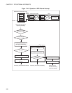
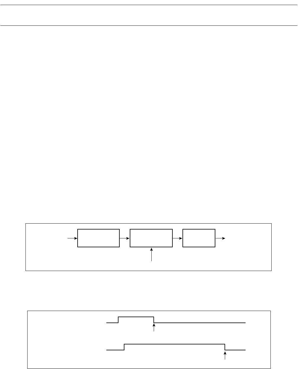
• When a level causing an interrupt factor is inputted with level detection set in the detection level setting
register, factor F/F in the DTP/external interrupt factor register is set to "1" and the factor is held as
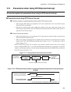
shown in Figure 17.5-1 .
With the factor held in factor F/F, the request to the interrupt controller remains active if the interrupt
request is enabled (ENIR1: EN = 1) even after the DTP/external interrupt factor is cancelled. To cancel the
request to the interrupt controller, clear the external interrupt request flag bit (EIRR1: ER) and clear the
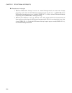
factor F/F as shown in Figure 17.5-2 .
Figure 17.5-1 Clearing Factor Hold Circuit when Level Set
Figure 17.5-2 DTP/External Interrupt Factor and Interrupt Request Generated when Interrupt Request
Enabled
DTP/ interrupt
input detection
circuit
DTP/external
interrupt factor
Factor F/F
(EIRR1 register)
Enable gate
To interrupt
controller
(interrupt request)
The factor remains held unless cleared.
DTP/external interrupt factor
(when High level detected)
Interrupt request issued
to interrupt controller
The interrupt request is inactived by clearing the factor F/F.
Interrupt factor cancelled


