


365
CHAPTER 18 8-/10-BIT A/D CONVERTER
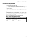
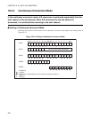
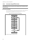
■ Operation of Pause-conversion Mode
• When the start trigger is inputted, A/D conversion starts at the channel set by the A/D conversion start
channel select bits (ANS3 to ANS0). The A/D conversion pauses at the termination of the A/D
conversion for one channel. When the start trigger is inputted while A/D conversion pauses, A/D
conversion for the next channel is performed.
• The A/D conversion pauses at the termination of the A/D conversion for the channel set by the A/D
conversion end channel select bits (ANE3 to ANE0). When the start trigger is inputted while A/D
conversion pauses, A/D conversion is continued after returning to the channel set by the A/D conversion
start channel select bits (ANS3 to ANS0).
• To restart this mode while A/D conversion pauses, input the start trigger set by the A/D start trigger
select bits in the A/D control status register (ADCS:STS1, STS0).
• To terminate A/D conversion forcibly, write 0 to the A/D conversion-on flag bit in the A/D control
status register (ADCS:BUSY).
• This mode cannot be restarted during A/D conversion.
[When start and end channels are the same]
If the start and end channels have the same channel number (ADCS:ANS3 to ANS0 = ADCS:ANE3 to
ANE0), A/D conversion for one channel set as the start channel (= end channel) and pause are repeated.
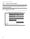
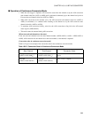
[Conversion order in pause-conversion mode]
Table 18.5-3 gives an example of the conversion order in the pause-conversion mode.
Table 18.5-3 Conversion Order in Pause-conversion Mode
Start Channel End Channel Conversion Order
AN0 pin
(ADCS: ANS="0000
B
")
AN3 pin
(ADCS: ANE="0011
B
")
AN0 → Stop, Start → AN1 → Stop, Start →
AN2 → Stop, Start → AN3 → Stop, Start →
AN0 → Repeat
AN3 pin
(ADCS: ANS="0011
B
")
AN3 pin
(ADCS: ANE="0011
B
")
AN3 → Stop, Start → AN3 → Stop, Start →
Repeat