


225
CHAPTER 13 16-Bit I/O TIMER
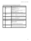
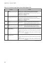
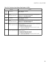
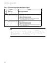
Table 13.3-5 Functions of Input Capture Edge Register 01 (ICE01)
Bit name Function
bit15
to
bit13
Undefined bits Read : The value is undefined.
Write: No effect.
bit12 ICUS1:
Input signal selection bit 1
This bit selects the input signal used as the trigger of the input capture 1.
When set to "0": Select the external pin IN1.
When set to "1": Select the IN-UART1.
bit11 Undefined bit Read : The value is undefined.
Write: No effect.
bit10 ICUS0:
Input signal selection bit 0
This bit selects the input signal used as the trigger of the input capture 0.
When set to "0": Select the external pin IN0.
When set to "1": Select the IN-UART0.
bit9 IEI1:
Detection edge indication bit 1
This bit indicated the edge detected by the input capture 1 (rising/falling).
This bit is read only.
"0": Indicate that falling edge is detected.
"1": Indicate that rising edge is detected.
Note: This bit value is disabled when the capture operation is stopped
(ICS01 : EG11, EG10="00").
bit8 IEI0:
Detection edge indication bit 0
This bit indicated the edge detected by the input capture 0 (rising/falling).
This bit is read only.
"0": Indicate that falling edge is detected.
"1": Indicate that rising edge is detected.
Note: This bit value is disabled when the capture operation is stopped
(ICS01 : EG01, EG00="00").