


518
CHAPTER 22 ADDRESS MATCH DETECTION FUNCTION
■ E
2
PROM Memory Map
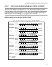
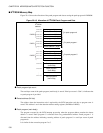
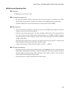
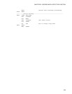
Figure 22.4-3 shows the allocation of the patch program and data at storing the patch program in E
2
PROM.
Figure 22.4-3 Allocation of E
2
PROM Patch Program and Data
●
Patch program byte count
The total byte count of the patch program (main body) is stored. If the byte count is "00
H
", it indicates that
no patch program is provided.
●
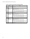
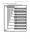
Detect address (24 bits)
The address where the instruction code is replaced by the INT9 instruction code due to program error is
stored. This address is set in the detection address setting registers (PADR0 to PADR5).
●
Patch program (main body)
The program executed by the INT9 interrupt processing when the program address matches the detect
address is stored. Patch program 0 is allocated from any predetermined address. Patch program 1 is
allocated from the address indicating <starting address of patch program 0 + total byte count of patch
program 0>.
It is similar for the correction program 2 to 5.
PADR0
PADR1
PADR5
0 0 0 0 H
0 0 0 1 H
0 0 0 2 H
0 0 0 3 H
0 0 0 4 H
0 0 0 5 H
0 0 0 6 H
0 0 0 7 H
0 0 1 4 H
0 0 1 6 H
0 0 1 5 H
0 0 1 7 H
0 0 2 0 H
0 0 3 0 H
0 0 7 0 H
E
2
PROM
address
Patch program byte count
Detect address 0 (Low)
Detect address 0 (Middle)
Detect address 0 (High)
Patch program byte count
Detect address 1 (Low)
Detect address 1 (Middle)
Detect address 1 (High)
Patch program byte count
Detect address 5 (Low)
Detect address 5 (Middle)
Detect address 5 (High)
Patch program 0
(main body)
Patch program 1
(main body)
Patch program 5
(main body)
For patch program 0
For patch program 1
For patch program 5
.
.
.
.
.
.
.
.
.
.
.
.