


323
CHAPTER 17 DTP/EXTERNAL INTERRUPTS
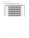
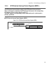
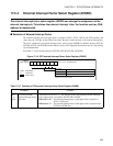
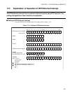
17.3.3 Detection Level Setting Register (ELVR1)
The detection level setting register sets the level or edge of input signals that cause the
interrupt factors of the DTP/external interrupt pin.
ELVR1 is corresponding to INT8, INT9R, INT10, INT11, INT12R, INT13, INT14R and
INT15R.
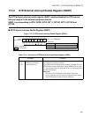
■ Detection Level Setting Register (ELVR1)
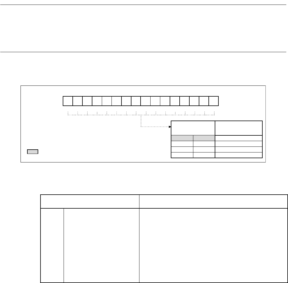
Figure 17.3-4 Detection Level Setting Register (ELVR1)
R/W
LB15,LA15,LB14,LA14,
LB13,LA13,LB12,LA12,
LB11,LA11,LB10,LA10,
LB9 ,LA9 ,LB8 ,LA8
0000000000000000BELVR1:0000CCB
1213 11 10 9 8
bit15 to bit0
14
15
R/WR/WR/WR/WR/WR/WR/WR/W
453210
6
7
R/WR/WR/WR/WR/WR/WR/WR/W
0
1
0
1
0
0
1
1
LB15LA15 LA14 LA13 LA12 LA11 LA10 LA9 LA8LB14 LB13 LB12 LB11 LB10 LB9 LB8
Reset value
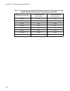
Detection condition
select bit
Low level detection
High level detection
Rising edge detection
Falling edge detection
Address
: Read/Write
: Reset value
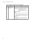
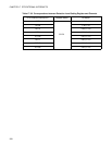
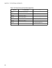
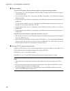
Table 17.3-5 Functions of Detection Level Setting Register (ELVR1)
Bit Name Function
bit15
to
bit0
ELVR1 ...
LB15, LA15 to LB8, LA8
Detection condition select
bits
These bits set the levels or edges of input signals from
external peripheral devices that cause interrupt factors in the
DTP/external interrupt pins.
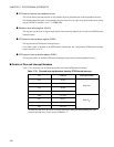
• Two levels or two edges are selectable for external
interrupts, and two levels are selectable for the EI
2
OS.
Reference:
When the set detection signal is input to the DTP/external
interrupt pins, the DTP/external interrupt request flag bits
are set to "1" even if DTP/external interrupt requests are
disabled (ENIR1:EN = 0).