316
CHAPTER 17 DTP/EXTERNAL INTERRUPTS
●
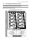
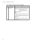
DTP/external interrupt input detection circuit
This circuit detects interrupt requests or data transfer requests generated from external peripheral devices.
The interrupt request flag bit corresponding to the pin whose level or edge set by the detection level setting
register (ELVR) is detected is set to "1" (EIRR1:ER).
●
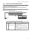
Detection level setting register (ELVR1)
This register sets the level or edge of input signals from external peripheral devices that cause DTP/external
interrupt factors.
●
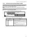
DTP/external interrupt factor register (EIRR1)
This register holds DTP/external interrupt factors.
If an enable signal is inputted to the DTP/external interrupt pin, the corresponding DTP/external interrupt
request flag bit is set to "1".
●
DTP/external interrupt enable register (ENIR1)
This register enables or disables DTP/external interrupt requests from external peripheral devices.
■ Details of Pins and Interrupt Numbers
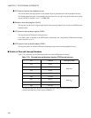
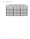
Table 17.2-1 shows the pins and interrupt numbers used in the DTP/external interrupt.
Table 17.2-1 Pins and Interrupt Numbers Used by DTP/External Interrupt
Pin Channel Interrupt number
P54 INT8
#26(1A
H
)
P42 INT9R
P55 INT10
P56 INT11
P80 INT12R
#28(1C
H
)
P57 INT13
P82 INT14R
P84 INT15R
INT9R, INT12R, INT14R, and INT15R are enabled by setting the corresponding bit of the
external interrupt factor select register (EISSR) to "1".


