


41
CHAPTER 2 CPU
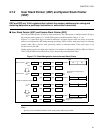
2.7.2 User Stack Pointer (USP) and System Stack Pointer
(SSP)
USP and SSP are 16-bit registers that indicate the memory addresses for saving and
restoring data when a push/pop instruction or subroutine is executed.
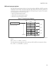
■ User Stack Pointer (USP) and System Stack Pointer (SSP)
The USP and SSP registers are used by stack instructions. The USP register is enabled when the S flag in
the processor status register is “0”, and the SSP register is enabled when the S flag is “1” (see
Figure 2.7-5 ). Since the S flag is set when an interrupt is accepted, register values are always saved in the
memory area indicated by SSP during interrupt processing. SSP is used for stack processing in an interrupt
routine, while USP is used for stack processing outside an interrupt routine. If the stack space is not
divided, use only the SSP.
During stack processing, the high-order eight bits of an address are indicated by SSB (for SSP) or USB (for
USP). USP and SSP are not initialized by a reset. Instead, they hold undefined values.
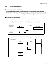
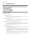
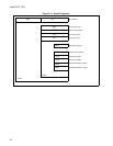
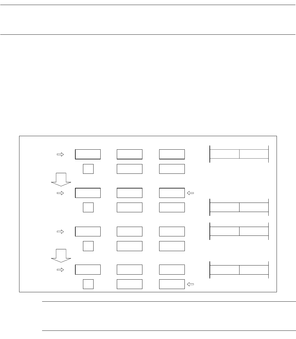
Figure 2.7-5 Stack Manipulation Instruction and Stack Pointer
Note:
Specify an even-numbered address in the stack pointer whenever possible.
AL A624
H
USB USP
SSPSSB0
C6
H
56
H
F328
H
1234
H
C6F326
H
MSB LSB
XX
XX
AL A624
H
USB USP
SSPSSB0
C6
H
56
H
F326
H
1234
H
C6F326
H
24
H
A6
H
AL A624
H
USB USP
SSPSSB
C6
H
56
H
F328
H
1234
H
561232
H
XX
XX
1
AL A624
H
USB USP
SSPSSB1
C6
H
56
H
F328
H
1232
H
561232
H
24
H
A6
H
Example of PUSHW A when S flag is "0"
Example of PUSHW A when S flag is "1"
Before execution
After execution
System stack is used because S
flag is "0".
System stack is used because
S flag is "1".
S flag