


354
CHAPTER 18 8-/10-BIT A/D CONVERTER
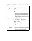
Note:
Do not set the A/D conversion mode set bits (MD1 and MD0) and A/D conversion end channel select bits
(ANE3, ANE2, ANE1 and ANE0) through read-modify-write commands after the start channel is set in
the A/D conversion start channel select bits (ANS3, ANS2, ANS1 and ANS0).
The ANS3, ANS2, ANS1 and ANS0 bits will read the last conversion channel until the A/D conversion
operation starts. Accordingly when the MD1 and MD0 bits and the ANE3, ANE2, ANE1 and ANE0 bits
are set through read-modify-write commands after the start channel is set in the ANS3, ANS2, ANS1 and
ANS0 bits, the values of the ANE3, ANE2, ANE1 and ANE0 bits may be rewritten.
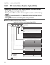
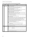
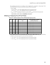
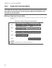
■ Setting of Sampling Time (ST2 to ST0 bits)
bit3
to
bit0
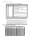
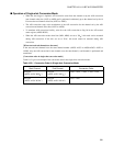
ANE3 to ANE0:
A/D conversion end
channel select bits
These bits set the channel at which A/D conversion terminated.
Start channel < end channel:
A/D conversion starts at channel set by A/D conversion start channel
select bits (ANS3 to ANS0) and terminates channel set by A/D
conversion end channel select bits (ANE3 to ANE0)
Start channel = end channel:
A/D conversion is performed only for one channel set by A/D
converter start (= end) channel select bits (ANE3 to ANE0 = ANS3 to
ANS0).
Start channel > end channel:
Do not set.
Continuous conversion mode and pause-conversion mode:
When A/D conversion terminated at the channel set by the A/D
conversion end channel select bits (ANE3 to ANE0), it returns to the
channel set by the A/D conversion start channel select bits (ANS3 to
ANS0).
Note:
Do not set the A/D conversion end channel select bits (ANE3 to
ANE0) during A/D conversion.
Table 18.3-5 Function of A/D Setting Register (ADSR0/ADSR1) (2/2)
Bit Name Function
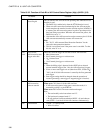
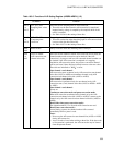
Table 18.3-6 Relation between ST2 to ST0 Bits and Sampling Time
ST2 ST1 ST0 Setting of Sampling
Time
Setting example (φ: Internal
operating frequency)
0 0 0 4 machine cycles φ= 8 MHz: 0.5 µs
0 0 1 6 machine cycles φ= 8 MHz: 0.75 µs
0 1 0 8 machine cycles φ= 16 MHz: 0.5 µs
0 1 1 12 machine cycles φ= 24 MHz: 0.5 µs
1 0 0 24 machine cycles φ= 8 MHz: 3 µs
1 0 1 36 machine cycles φ= 16 MHz: 2.25 µs
1 1 0 48 machine cycles φ= 16 MHz: 3.0 µs
1 1 1 128 machine cycles φ= 24 MHz: 5.3 µs