


321
CHAPTER 17 DTP/EXTERNAL INTERRUPTS
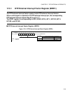
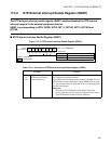
17.3.2 DTP/External Interrupt Enable Register (ENIR1)
The DTP/external interrupt enable register (ENIR1) enables/disables the DTP/external
interrupt request in the external peripheral devices.
ENIR1 is corresponding to INT8, INT9R, INT10, INT11, INT12R, INT13, INT14R and
INT15R.
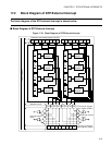
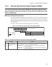
■ DTP/External Interrupt Enable Register (ENIR1)
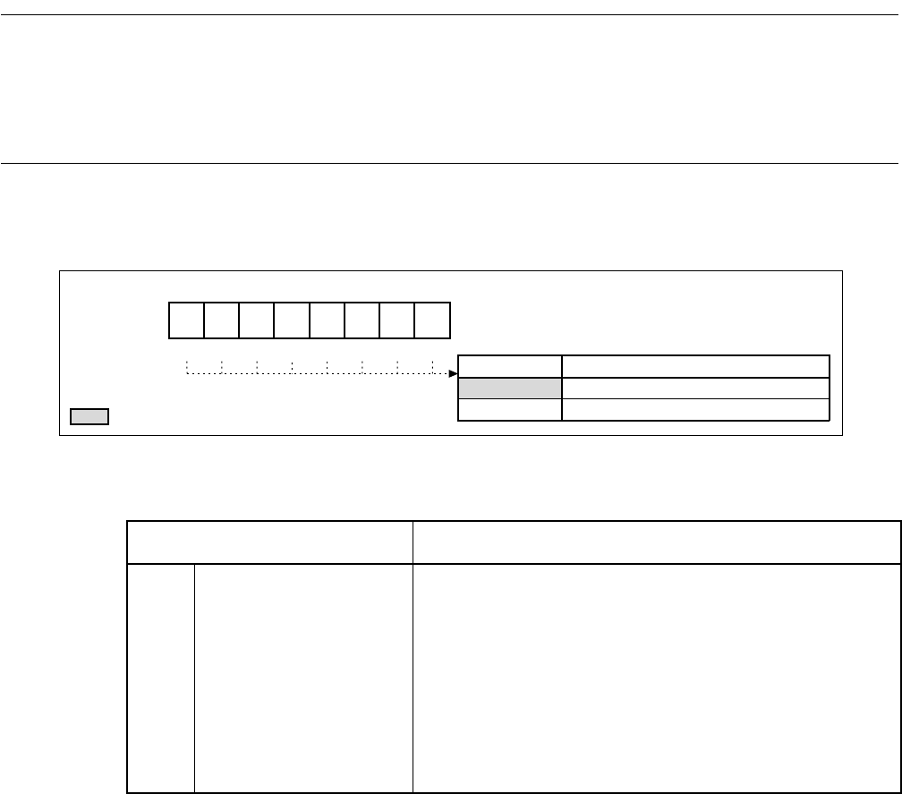
Figure 17.3-3 DTP/External Interrupt Enable Register (ENIR1)
R/W
ENIR1: 0000CAH
00000000B
453210
bit7 to bit0
6
7
R/WR/WR/WR/WR/WR/WR/WR/W
0
1
EN15 to EN8
EN15 EN14 EN13EN12 EN11 EN10 EN9 EN8
Address
Reset value:
: Read/Write
: Reset value
DTP/external interrupt request enable bit
DTP/external interrupt enable
DTP/external interrupt disable
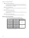
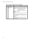
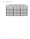
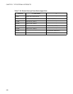
Table 17.3-3 Functions of DTP/External Interrupt Enable Register (ENIR1)
Bit Name Function
bit0
to
bit7
EN15 to EN8(ENIR1),
DTP/external interrupt
request enable bits
These bits enable or disable the DTP/external interrupt request to
the DTP/external interrupt channel.
If the DTP/external interrupt request enable bit (ENIR1:EN) and
the DTP/external interrupt request flag bit (EIRR1:ER) are set to
"1", the interrupt request is generated to the corresponding DTP/
external interrupt pin.
Reference:
The state of the DTP/external interrupt pin can be read
directly using the port data register irrespective of the setting
of the DTP/external interrupt request enable bit.