


426
CHAPTER 20 LIN-UART
20.7.2 Operation in Synchronous Mode (Operation Mode 2)
The clock synchronous transfer method is used for LIN-UART operation mode 2 (normal
mode).
■ Operation in Synchronous Mode (Operation mode 2)
●
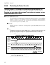
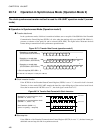
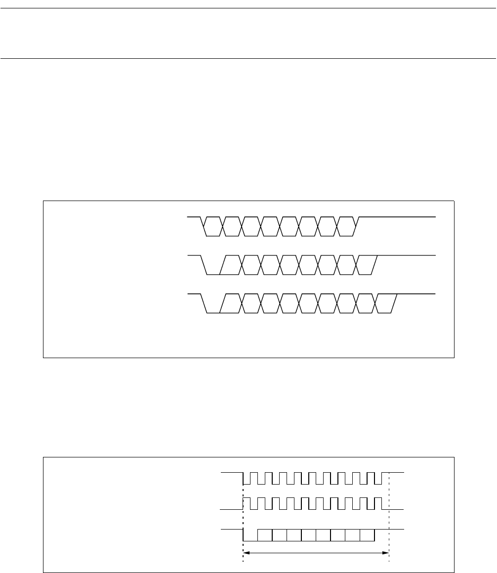
Transfer data format
In the synchronous mode, 8-bit data is transferred without start or stop bits if the SSM bit of the Extended
Communication Control Register (ECCR) is 0. Also, when the start/stop bit is provided (ECCR: SSM = 1),
presence or absence of the parity bit can be selected (SCR: PEN). The figure below illustrates the data
format during a transmission in the synchronous operation mode.
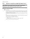
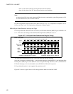
Figure 20.7-3 Transfer Data Format (operation mode 2)
●
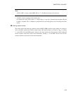
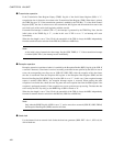
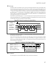
Clock inversion function
If the SCES bit of the Extended Status/Control Register (ESCR) is set to "1", the serial clock is inverted.
Therefore, in slave mode LIN-UART samples the data bits at the falling edge of the received serial clock.
Note, that in master mode if SCES is set to "1", the clock signal’s mark level is "0".
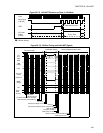
Figure 20.7-4 Transfer Data Format with Clock Inversion
●
Start/stop bits
If the SSM bit of the Extended Communication Control Register (ECCR) is set to "1", the data format gets
additional start and stop bits like in asynchronous mode.
*
*
(ECCR:SSM=0,SCR:PEN=0)
(ECCR:SSM=1,SCR:PEN=0)
(ECCR:SSM=1,SCR:PEN=1)
D0 D1 D2 D3 D4 D5 D6 D7
ST D0 D1 D2 D3 D4 D5 D6 D7
ST D0 D1 D2 D3 D4 D5 D6 D7 P SP SP
SP SP
Reception or transfer data
Reception or transfer data
Reception or transfer data
*: Set to 2-stop bits (SCR: SBL = 1)
ST: Start bit SP: Stop bit P: Parity bit LSB first
data frame
Reception or transmission clock
Data stream (SSM = 1)
(here: no parity, 1 stop bit)
ST
SP
(SCES = 0, CCO = 0):
Reception or transmission clock
(SCES = 1, CCO = 0):
mark level
mark level