


514
CHAPTER 22 ADDRESS MATCH DETECTION FUNCTION
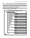
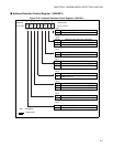
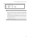
■ Functions of Detect Address Setting Registers
• There are six detect address setting registers (PADR0 to PADR5) that consist of a high byte (bank),
middle byte, and low byte, totaling 24 bits.
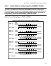
• In the detect address setting registers (PADR0 to PADR5), starting address (first byte) of instruction to
be replaced by INT9 instruction should be set.
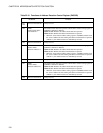
Table 22.3-3 Address Setting of Detect Address Setting Registers
Register Name
Interrupt
Output
Enable
Address Setting
Detect address setting
register 0
(PADR0)
PACSR0:
AD0E
High Set the upper 8 bits of detect address 0 (bank).
Middle Set the middle 8 bits of detect address 0.
Low Set the lower 8 bits of detect address 0.
Detect address setting
register 1
(PADR1)
PACSR0:
AD1E
High Set the upper 8 bits of detect address 1 (bank).
Middle Set the middle 8 bits of detect address 1.
Low Set the lower 8 bits of detect address 1.
Detect address setting
register 2
(PADR2)
PACSR0:
AD2E
High Set the upper 8 bits of detect address 2 (bank).
Middle Set the middle 8 bits of detect address 2.
Low Set the lower 8 bits of detect address 2.
Detect address setting
register 3
(PADR3)
PACSR1:
AD3E
High Set the upper 8 bits of detect address 3 (bank).
Middle Set the middle 8 bits of detect address 3.
Low Set the lower 8 bits of detect address 3.
Detect address setting
register 4
(PADR4)
PACSR1:
AD4E
High Set the upper 8 bits of detect address 4 (bank).
Middle Set the middle 8 bits of detect address 4.
Low Set the lower 8 bits of detect address 4.
Detect address setting
register 5
(PADR5)
PACSR1:
AD5E
High Set the upper 8 bits of detect address 5 (bank).
Middle Set the middle 8 bits of detect address 5.
Low Set the lower 8 bits of detect address 5.