


369
CHAPTER 18 8-/10-BIT A/D CONVERTER
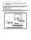
18.6 Precautions when Using 8-/10-bit A/D Converter
Precautions when using the 8-/10-bit A/D converter are given below:
■ Precautions when Using 8-/10-bit A/D Converter
●
Analog input pin
• The analog input pins serve as general-purpose I/O ports of port 5 and port 6. When using the pin as an
analog input pin, switch the pin to "analog input pin" according to the setting of the analog input enable
register (ADER5 , ADER6).
• When using the pin as an analog input pin, write 1 to the bit in the analog input enable register (ADER5,
ADER6) corresponding to the pin to be used and set the pin to "analog input enable".
• When an intermediate-level signal is inputted with the pin set as a general-purpose I/O port, the input
leakage current flows in the gate. When using the pin as an analog input pin, always set the pin to
"analog input enable".
●
Precaution when starting by external trigger
• Set the level of the external trigger to inactive ("H" for external trigger) when the A/D start trigger select
bits in the A/D control status register (ADCS: STS1 and STS0) is set the same way as starting the 8-/10-
bit A/D converter by the external trigger. Holding the input value for the start trigger active may cause
the 8-/10-bit A/D converter to start the A/D start trigger select bits in the A/D control status register
(ADCS: STS1 and STS0).
●
Procedure of 8-/10-bit A/D converter and analog input power-on
• Always apply a power to the 8-/10-bit A/D converter power (AV CC , AVR) and the analog input (AN0
to AN15 pins) after or concurrently with the digital power (V
CC
)-on.
• Always turn off the 8-/10-bit A/D converter power and the analog input before or concurrently with the
digital power (V
CC
)-down.
• Note that AVR should not exceed AV
CC
at power on or power down. (Turning on and off the analog
power and digital power simultaneously is enabled.)
●
Power supply voltage of 8-/10-bit A/D converter
• To prevent latch up, note that the 8-/10-bit A/D converter power (AV
CC
) should not exceed the digital
power (V
CC
) voltage.