211
CHAPTER 13 16-Bit I/O TIMER
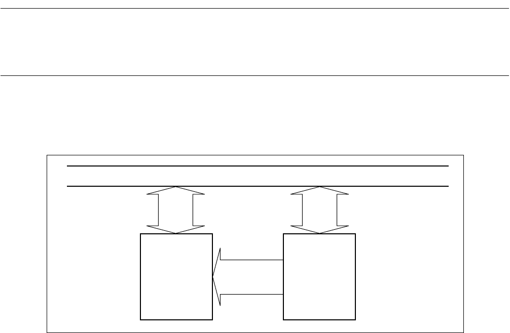
13.2 Block Diagram of 16-bit I/O Timer
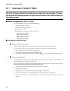
The 16-bit I/O timer consists of the following modules:
• 16-bit free-run timer
• Input capture
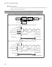
■ Block Diagram of 16-bit I/O Timer
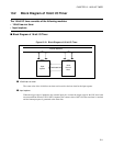
Figure 13.2-1 Block Diagram of 16-bit I/O Timer
●
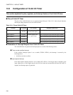
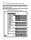
16-bit free-run timer
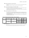
The count value of the 16-bit free-run timer can be used as the base time for the input capture.
●
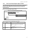
Input capture
When the trigger edge is inputted to the external input pin, or when the trigger edge for the LIN slave baud
rate measurement from the LIN-UART is inputted, the counter value of the 16-bit free-run timer is retained
and the interrupt request is generated at the same time.
Internal data bus
Input
capture
16-bit
free-run
timer
Dedicated bus


