


203
CHAPTER 12 WATCHDOG TIMER
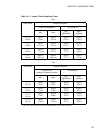
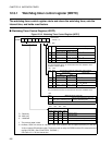
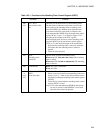
Table 12.3-1 Functions of the Watching Timer Control Register (WDTC)
Bit name Function
bit0
bit1
WT1, WT0:
Interval time select
bits
These bits set the interval time of the watchdog timer.
The time interval when the watch timer is used as the
clock source to the watchdog timer (watchdog clock
select bit WDCS= 0) is different from when the main
clock mode or the PLL clock mode is selected as the
clock mode and the WDCS bit in the watch timer control
register (WTC) is set to "1" as shown in Figure 12.3-2
according to the settings of the WTC register.
In the subclock mode, be sure to set the watchdog clock
select bit (WDCS) in the watch timer control register
(WTC) to "0" and select the output of the watch timer.
• Data after the watchdog timer is started is valid only.
• Write data after the watchdog timer is started is
ignored.
• These are write-only bits.
bit2 WTE:
Watchdog timer
control bit
This bit starts or clears the watchdog timer.
When set to "0" (first time after reset): The watchdog
timer is started.
When set to "0" (second or subsequent): The watchdog
timer is cleared.
bit6 Undefined bit Read: The value is undefined.
Write: No effect
bit3
to
bit5,
bit7
PONR, WRST, ERST,
SRST:
Reset factor bits
These bits indicate reset factors.
• When a reset occurs, the bit corresponding to the reset
factor is set to "1". After a reset, the reset factor can be
checked by reading the watchdog timer control register
(WDTC).
• These bits are cleared after the watchdog timer control
register (WDTC) is read.
Note: No bit value other than the PONR bit after power-
on reset is assured. If the PONR bit is set at read,
other bit values should be ignored.