329
CHAPTER 17 DTP/EXTERNAL INTERRUPTS
■ DTP/External Interrupt Operation
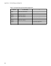
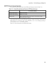
The control bits and the interrupt factors for the DTP/external interrupt are shown in Table 17.4-1 .
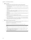
If the interrupt request signal from the DTP/external interrupt is output to the interrupt controller and the
EI
2
OS enable bit in the interrupt control register (ICR:ISE) is set to "0", the interrupt processing is
executed. This bit is set to "1", the EI
2
OS is executed.
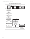
Figure 17.4-2 shows the operation of the DTP/external interrupt.
Table 17.4-1 Control Bits and Interrupt Factors for DTP/External Interrupt
DTP/External interrupt
Interrupt request flag bit EIRR1: ER15 to ER8
Interrupt request enable bit ENIR1: EN15 to EN8
Interrupt factor Input of valid edge or level to INT13, INT11, INT10, INT8 , INT9R,
INT12R, INT14R, INT15R pins


