


519
CHAPTER 22 ADDRESS MATCH DETECTION FUNCTION
■ Setting and Operating State
●
Initialization
E
2
PROM data are all cleared to "00
H
".
●
Occurrence of program error
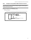
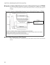
• By using the connector (UART), information about the patch program is transmitted to the MCU
(F
2
MC16LX) from the outside according to the allocation of the E
2
PROM patch program and data.
•The MCU (F
2
MC16LX) stores the information received from outside in the E
2
PROM.
●
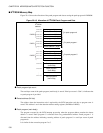
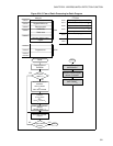
Reset sequence
• After reset, the MCU (F
2
MC16LX) reads the byte count of the E
2
PROM patch program to check the
presence or absence of the correction program.
• If the byte count of the patch program is not "00
H
", the higher, middle and lower bits at detect addresses
0 to 5 are read and set in the detection address setting registers 0 to 5 (PADR0 to PADR5). The patch
program (main body) is read according to the byte count of the patch program and written to RAM in
the MCU (F
2
MC16LX).
• The patch program (main body) is allocated to the address where the patch program is executed in the
INT9 interrupt processing by the address match detection function.
• Address match detection is enabled (PACSR: AD0E=1, AD1E=1 ... AD5E=1).
●
INT9 Interrupt processing
• Interrupt processing is performed by the INT9 instruction. The MB90360 series has no interrupt request
flag by address match detection. Therefore, if the stack information in the program counter is discarded,
the detect address cannot be checked. When checking the detect address, check the value of program
counter stacked in the interrupt processing routine.
• The patch program is executed, branching to the normal program.