


137
CHAPTER 8 LOW-POWER CONSUMPTION MODE
8.2 Block Diagram of the Low-Power Consumption Control
Circuit
This section shows the block diagram of the low-power consumption control circuit.
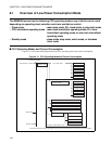
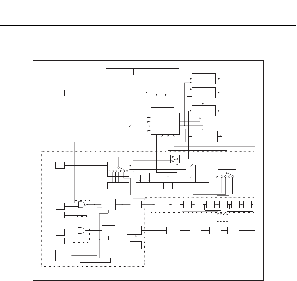
■ Block Diagram of the Low-Power Consumption Control Circuit
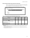
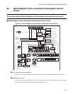
Figure 8.2-1 Block Diagram of the Low-Power Consumption Control Circuit
●
CPU intermittent operation selector
This selector selects the halt cycle count of the CPU clock during the CPU intermittent operation mode.
●
Standby control circuit
CPU clock control and peripheral clock control circuits switch the CPU operation clock and peripheral
function operation clock to transit to and cancel the standby mode.
2-
divided
512-divided
2-
divided
2-
divided
X0
2
X1
RST
STP RSTSLP CG1 CG0
Re-
served
SPL TMD
SCM
WS0
MCM MCS CS1 CS0WS1
SCS
2
2
8-divided
1024
-divided
2-divided 2-divided
X0A
X1A
4-
divided
2-
divided
2-
ivided
4-
divided
CS2
SCDS
* : MB90367/T(S)
*
*
Watch timer
Timebase timer
Main
clock
To watchdog timer
Clock supervisor
Subclock
oscillation
circuit
Internal CR
oscillation
clock
Clock
selector
Clock
selector
2
-divided
Oscillation
clock (HCLK)
Sub-clock
(HCLK)
PLL/subclock
control register
(PSCCR):bit10
4-divided/
2-divided
Oscillation clock
generator
Pin
Pin
Pin
Pin
Clock select register (CKSCR)
PLL multiplier
circuit
Clock
generator
PLL/subclock
control register
(PSCCR): bit8
Operation clock
selector
Interrupt
(cancellation)
Pin
Reset
(cancellation)
Low-power consumption mode control register (LPMCR)
Pin High-Z
control circuit
Pin Hi-Z control
Internal reset
Select the intermitted cycle
CPU operating clock
Watch, sleep and stop signal
Watch and stop signal
Internal reset
generator
CPU clock
control circuit
Peripheral clock
control circuit
Resources
operating clock
CPU intermittent
operation cycle
selector
Standby
control circuit
Cancellation of subclock oscillation stabilization wait
Cancellation of main clock oscillation stabilization wait
Machine clock
Oscillation
stabilization
selector