


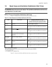
126
CHAPTER 7 RESETS
7.4 Reset Operation
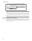
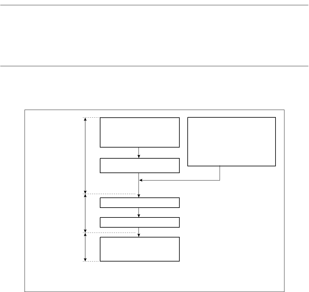
When the reset signal is inactivated, the reset vector and mode data is fetched from the
predetermined locations depending on the setting of the mode pins. This operation, the
mode fetch, then defines the operation mode of the CPU and the start address of the
first instruction. For the power on reset, reset from the stop mode or sub-clock mode,
the mode fetch is performed after the oscillation stabilization wait time is elapsed.
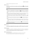
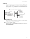
■ Overview of Reset Operation
Figure 7.4-1 shows the reset operation flow.
Figure 7.4-1 Reset Operation Flow
■ Mode Pins
Setting the mode pins (MD0 to MD2) specifies how to fetch the reset vector and the mode data. Fetching
the reset vector and the mode data is performed in the reset sequence. See "9.1.1 Mode Pins", for details on
mode pins.
External reset
Software reset
Watchdog timer reset
Low voltage detection reset*
1
CPU operation detection reset*
1
Clock supervisor reset*
2
Power-on reset
Stop mode
Sub-clock mode
Oscillation stabilization wait
reset status
Fetch reset vector
Fetch mode data
Fetch the instruction code from
the address indicated by the reset
vector and execute instruction
D
uring reset
M
ode fetch
(
reset operation)
N
ormal operation
(
RUN status)
*1: Product with T-suffix
*2: For MB90F367/T(S), MB90367/T(S)