


61
CHAPTER 3 INTERRUPTS
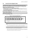
3.3 Interrupt Control Registers (ICR)
The interrupt control registers are in the interrupt controller. Each interrupt control
register has a corresponding I/O that has an interrupt function. The interrupt control
registers have the following 3 functions:
• Setting an interrupt level for corresponding peripherals
• Selecting whether to use an ordinary interrupt or extended intelligent I/O service for
the corresponding peripherals
• Selecting the extended intelligent I/O service channel
Do not access an interrupt control register by using a read-modify-write instruction, as
doing so causes a misoperation.
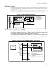
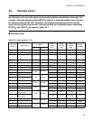
■ Interrupt Control Register (ICR)
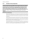
Figure 3.3-1 is a diagram of the bit configuration of an interrupt control register.
Figure 3.3-1 Interrupt Control Register (ICR)
Note:
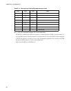
ICS3 to ICS0 are valid only when EI
2
OS is activated. Set
'1' in ISE to activate EI
2
OS, and set '0' in ISE
not to activate it. When EI
2
OS is not to be activated, any value can be set in ICS3 to ICS0.
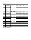
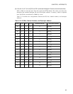
[bit 10 to bit 8, bit 2 to bit 0] IL0, IL1, and IL2 (interrupt level setting bits)
These bits are readable and writable and specify the interrupt level of the corresponding internal
resources. Upon a reset, these bits are initialized to level 7 (no interrupt). Table 3.3-1 describes the
relationship between the interrupt level setting bits and interrupt levels.
Interrupt control
register
00000111
B
when reset
ISE
15/7
ICS1ICS3
or
S1
ICS0
or
S0
W R/WR/W
14/6 13/5 12/4 11/3 10/2 9/1 8/0
R/WR/W**W
ICS2 IL0IL1IL2
*: '1' is read always.
ICS1 and ICS0 are valid for write only. S1 and S0 are valid for read only.