


123
CHAPTER 7 RESETS
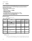
7.2 Reset Cause and Oscillation Stabilization Wait Times
The MB90360 series has seven reset causes. The oscillation stabilization wait time for a
reset depends on the reset cause.
■ Reset Causes and oscillation Stabilization Wait Times
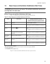
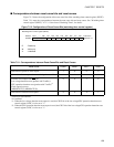
Table 7.2-1 summarizes reset causes and oscillation stabilization wait times.
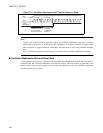
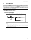
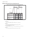
Figure 7.2-1 shows the oscillation stabilization wait times at a power-on reset.
Table 7.2-1 Reset Causes and oscillation Stabilization Wait Times
Reset Reset cause Oscillation stabilization wait time
The parenthesized values are provided when
oscillation clock frequency operates at 4 MHz
Power-on Power-on
2
16
/HCLK (approx. 16.38 ms)
Watchdog Watchdog timer overflow None
Note: However, the WS1 and WS0 bits are initialized to
"11".
External L input from RST
pin None
Note: However, the WS1 and WS0 bits are initialized to
"11".
Software Write "0" to RST bit of low-power
consumption mode control register
(LPMCR)
None
Note: However, the WS1 and WS0 bits are initialized to
"11".
Low voltage
detection *
1
When low voltage is detected None
Note: However, the WS1 and WS0 bits are initialized to
"11".
CPU operation
detection *
1
When CPU operation detection counter
overflows
None
Note: However, the WS1 and WS0 bits are initialized to
"11".
Clock supervisor *
2
When failure of main clock/subclock is
detected
None
Note: However, the WS1 and WS0 bits are initialized to
"11".
HCLK: Oscillation clock frequency
WS1, WS0: Oscillation stabilization wait time select bit of clock selection register (CKSCR)
*1: Product with T-suffix
*2: For MB90F367/T(S), MB90367/T(S)