398
CHAPTER 20 LIN-UART
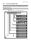
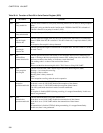
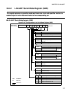
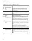
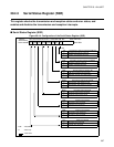
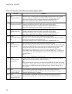
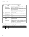
Table 20.4-3 Function of Each Bit in Serial Status Register (SSR)
No. Bit name Function
bit15 PE:
Parity error flag bit
•
This bit is set to 1 when a parity error occurs during reception at PE=1 and is cleared
when 1 is written to the CRE bit of the LIN-UART serial control register (SCR).
•
A reception interrupt request is outputted when this bit and the RIE bit are 1.
•
Data in the reception data register (RDR) is invalid when this flag is set.
bit14 ORE:
Overrun error flag bit
•
This bit is set to 1 when an overrun error occurs during reception and is cleared when 1 is
written to the CRE bit of the LIN-UART serial control register (SCR).
•
A reception interrupt request is outputted when this bit and the RIE bit are 1.
•
Data in the reception data register (RDR) is invalid when this flag is set.
bit13 FRE:
Framing error flag
bit
•
This bit is set to 1 when a framing error occurs during reception and is cleared when 1 is
written to the CRE bit of the LIN-UART serial control register (SCR).
•
A reception interrupt request is outputted when this bit and the RIE bit are 1.
•
Data in the reception data register (RDR) is invalid when this flag is set.
bit12 RDRF:
Receive data full flag
bit
•
This flag indicates the status of the reception data register (RDR).
•
This bit is set to 1 when reception data is loaded into RDR and can only be cleared to 0
when the reception data register (RDR) is read.
•
A reception interrupt request is outputted when this bit and the RIE bit are 1.
bit11 TDRE:
Transmission data
empty flag bit
•
This flag indicates the status of the transmission data register (TDR).
•
This bit is cleared to 0 when transmission data is written to TDR and indicates that valid
data exists in TDR. This bit is set to 1 when data is loaded into the transmission shift
register and transmission start and indicates that no valid data exists in TDR.
•
A transmission interrupt request is generated if both this bit and the TIE bit are 1.
•
If the LBR bit in the ECCR register is set to "1" while the TDRE bit is "1", then this bit
once changes to "0". After the completion of LIN synch break generator, the TDRE bit
changes back to "1".
Note:
This bit is set to 1 (TDR empty) as its initial value.
bit10 BDS:
Transfer direction
selection bit
•
This bit selects whether to transfer serial data from the least significant bit (LSB first,
BDS=0) or the most significant bit (MSB first, BDS=1).
Note:
The high-order and low-order sides of serial data are interchanged with each other during
reading from or writing to the serial data register. If this bit is set to another value after the
data is written to the RDR register, the data becomes invalid. This bit is fixed to "0" in
mode 3 (LIN).
bit9 RIE:
Reception interrupt
request enable bit
•
This bit enables or disables the reception interrupt request output to the CPU.
•
If any of the RDRF, PE, ORE and FRE bits is set to "1" and this bit is "1", then a
reception interrupt request is outputted.
bit8 TIE:
Transmission request
interrupt enable bit
•
This bit enables or disables the transmission interrupt request output to the CPU.
•
A transmission interrupt request is outputted when this bit and the TDRE bit are 1.


