


199
CHAPTER 12 WATCHDOG TIMER
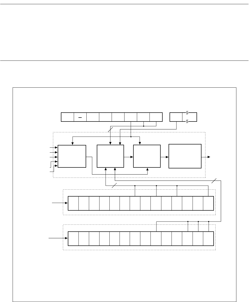
12.2 Configuration of Watchdog Timer
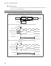
The watchdog timer consists of the following blocks:
• Count clock selector
• Watchdog timer counter (2-bit counter)
• Watchdog reset generator
• Counter clear control circuit
• Watchdog timer control register (WDTC)
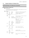
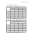
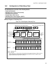
■ Block Diagram of Watchdog Timer
Figure 12.2-1 Block Diagram of Watchdog Timer
×
2
1
×
2
2
×
2
11
×
2
12
×
2
13
×
2
14
×
2
15
×
2
16
×
2
17
×
2
18
×
2
10
×
2
9
×
2
8
⋅ ⋅ ⋅
2
SRST
WT1
WT0
WTE
PONR
WRST
ERST
WDCS
×
2
1
×
2
2
×
2
8
×
2
9
×
2
10
×
2
11
×
2
12
×
2
13
×
2
14
×
2
15
×
2
7
×
2
6
×
2
5
⋅ ⋅ ⋅
4
4
Counter
clear control
circuit
Watchdog timer control register (WDTC)
Watch timer control register (WTC
)
Watchdog reset
generation
circuit
2-bit
counter
Count clock
selector
Generation of reset
Shift to sleep mode
(Timebase timer counter)
(Watch counter)
HCLK : Oscillation clock
SCLK : Sub clock
* : SCLK is 2 division or 4 division of the clock inputted to the low-speed oscillation pin (X0A and X1A) or
internal CR oscillation clock. The division ratio is set by the SCDS bit of the PLL/subclock control
register (PSCCR). (See "CHAPTER 5 CLOCKS".)
Main clock
(2 division of HCLK)
Shift to timebase
timer mode
Shift to watch mode
Shift to stop mode
To internal
reset
generation
circuit
Watchdog timer
Start up
Clear
Sub clock
SCLK*