


308
CHAPTER 16 8-/16-BIT PPG TIMER
●
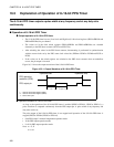
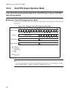
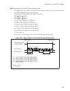
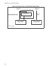
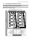
Operation in 8+8-bit PPG output operation mode
• The PPGn operates as the prescaler of the PPGm timer and the PPGm operates using the PPGn output as
a clock source.
• When the pin output is enabled (PPGCn: PE0=1, PPGCm: PE1=1) if PPG output pin selection is set to
standard (PPGnm:REV=0), PPGn pulse wave is outputted from the PPGn pin and the PPGm pulse wave
is outputted from the PPGm pin. When the PPG output pin is switched (PPGnm:REV=1), the output
pins PPGn and PPGm are switched.
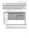
• When the reload value is set in the PPG reload registers (PRLLn/PRLHn, PRLLm/PRLHm) to enable
operation of the PPG timer (PPGCn:PEN0=1 and PPGCm: PEN1=1), the PPG down counter starts
counting.
• To stop the count operation of the PPG down counters, disable the operation of the PPG timers of both
channels (PPGCn: PEN0=0 and PPGCm: PEN1=0). The count operation of the PPG down counters is
stopped and the output of the PPG output pin is held at a Low level.
• If the PPG down counter of each channel underflows, the reload values set in the PPG reload registers
(PRLLn/PRLHn, PRLLm/PRLHm) are reloaded to the PPG down counter that underflows.
• When an underflow occurs, the underflow generation flag bit in the channel that causes an underflow
(PPGCn:PUF0=1, PPGCm:PUF1=1) is set. If an interrupt request is enabled at the channel that causes
an underflow (PPGCn: PIE0=1, PPGCm: PIE1=1), an interrupt request is generated.
Notes:
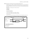
• Do not operate PPGm (PPGCm:PEN1 = 1) when PPGn is stopped (PPGCn:PEN0 = 0).
• It is recommended to set the same value in both Low-level and High-level PPG reload registers (PRLLn/
PRLHn, PRLLm/PRLHm).
Note: n = C, E
m = n+1