


395
CHAPTER 20 LIN-UART
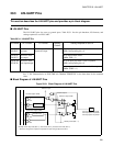
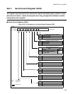
20.4.2 LIN-UART Serial Mode Register (SMR)
This register selects an operation mode and baud rate clock and specifies whether to
enable output of serial data and clocks to the corresponding pin.
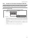
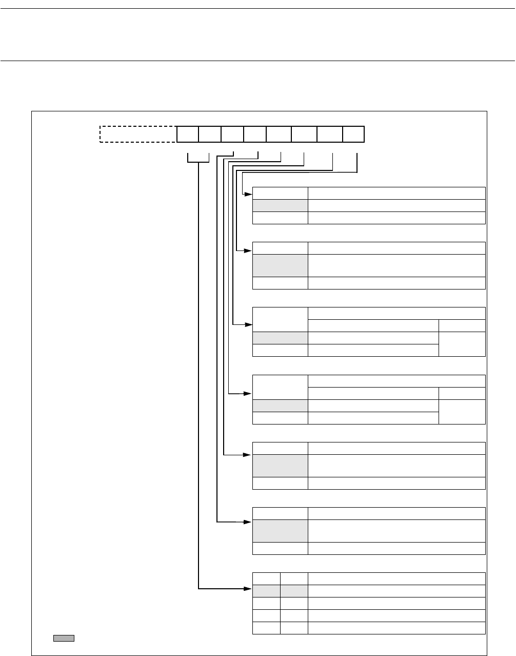
■ LIN-UART Serial Mode Register (SMR)
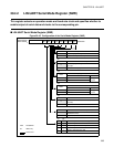
Figure 20.4-3 Configuration of the Serial Mode Register (SMR)
MD1
MD0
OTO
EXT
REST
UPCL SCKE SOE
bit7
R/W R/W R/W R/W W W R/W R/W
00000000
B
S
MR0:000020
H
S
MR1:000028
H
bit0
bit1
bit2
bit3bit4
bit6
bit5
bit15 bit8
R/W : Read/Write
W : Write only
: Initial value
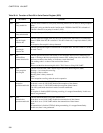
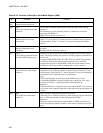
bit0
SOE Serial data output enable bit of LIN-UART
0 General-purpose I/O port
1 Serial data output enable pin of LIN-UART
bit1
SCKE LIN-UART serial clock output enable bit
0
General-purpose I/O port or LIN-UART clock
input pin
1 Serial clock output pin of LIN-UART
bit2
UPCL
LIN-UART programmable clear bit
write read
0 Ignored
always
read 0
1 Reset LIN-UART
bit3
REST
Restart dedicated Reload Counter bit
write read
0 Ignored
always
read 0
1 Restart Counter
bit4
EXT External Serial Clock Source select bit
0
Use internal Baud Rate Generator (Reload
Counter)
1 Use external Serial Clock Source
bit5
OTO One-to-one external clock Input enable bit
0
Use external Clock with Baud Rate Generator
(Reload Counter)
1 Use external Clock as it is
bit7 bit6
MD1 MD0
Operation Mode Setting bit
0 0 Mode 0: Asynchronous normal
0 1 Mode 1: Asynchronous Multiprocessor
1 0 Mode 2: Synchronous
1 1 Mode 3: Asynchronous LIN
Initial value
Address