


42
CHAPTER 2 CPU
2.7.3 Processor Status (PS)
The PS register consists of the bits controlling the CPU operation and the bits
indicating the CPU status.
■ Processor Status (PS)
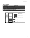
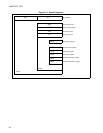
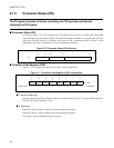
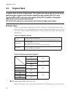
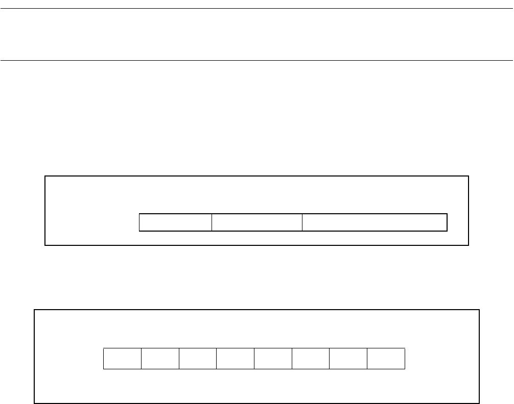
As shown in Figure 2.7-6 , the high-order byte of the PS register consists of a register bank pointer (RP)
and an interrupt level mask register (ILM). The ILM indicates the start address of a register bank. The low-
order byte of the PS register is a condition code register (CCR), containing the flags to be set or reset
depending on the results of instruction execution or interrupt occurrences.
Figure 2.7-6 Processor Status (PS) Structure
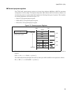
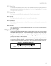
■ Condition Code Register (CCR)
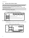
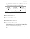
Figure 2.7-7 is a diagram of condition code register (CCR) configuration.
Figure 2.7-7 Condition Code Register (CCR) Configuration
●
I: Interrupt enable flag:
Interrupt requests other than software interrupts are enabled when the I flag is 1 and are masked when the I
flag is 0. The I flag is cleared by a reset.
●
S: Stack flag:
When the S flag is 0, USP is enabled as the stack manipulation pointer.
When the S flag is 1, SSP is enabled as the stack manipulation pointer.
The S flag is set by an interrupt reception or a reset.
15 13 12 8 7 0
PS ILM RP CCR
76543210
- ISTNZVC : CCR
Initial value - 0 1****** : Undefined