


175
CHAPTER 10 I/O PORTS
10.2.4 Analog Input Enable Register (ADER)
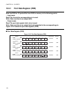
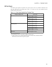
Figure 10.2-6 shows the analog input enable register.
■ Analog Input Enable Registers (ADER)
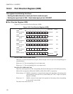
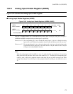
Figure 10.2-6 Analog Input Enable Registers (ADER6, ADER5)
Each bit of ADER6/ADER5 sets to enable/disable the analog input of each pin in the port 6 and port 5.
ADER6 and ADER5 correspond to the port 6 and port 5, respectively.
When set to "0": The corresponding pin is set to disable the analog input. A pin set to disable the analog
input can be used as I/O pin for peripheral function other than I/O port and A/D converter.
When set to "1": The corresponding pin is set to the analog input mode. A pin set to the analog input mode
is the dedicated analog input pin for the A/D converter. The pin cannot be used as I/O pin
of I/O port and other peripheral function.
Note:
When the analog input enable bit (ADEx) is set to "1", each pin of the port 6 and port 5 is the analog
input pin for the A/D converter. Initial value of the ADEx bit is "1". Therefore, the corresponding pins
cannot be used as I/O pin of peripheral function other than I/O port and A/D converter at the initial
setting. When the pin is used as I/O pin of other peripheral function and I/O port, the ADEx bit is set to
"0".
ADER6 7 6 5 4 3 2 1 0
ADE7 ADE6 ADE5 ADE4 ADE3 ADE2 ADE1 ADE0
11111111
B
R/W
ADER5
ADE15 ADE14 ADE13 ADE12 ADE11 ADE10 ADE9 ADE8
11111111
B
R/W
15 14 13 12 11 10 9 8
Initial value Access
Address: 00000C
H
Address: 00000B
H
R/W: Read/Write