


377
CHAPTER 19 LOW VOLTAGE DETECTION/CPU OPERATING DETECTION RESET
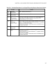
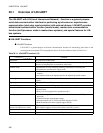
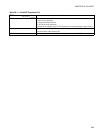
Table 19.3-1 Functional Description of Low Voltage/CPU operating Detection Reset Control Register
Bit name Function
bit7/
bit6
Reserved:
Reserved bits
Note: These bits should write "0".
bit5/
bit4
Reserved:
Reserved bits
Note: These bits should write "1".
bit3 CL:
CPU operating
detection clear bit
This bit is a bit that clears the counter of CPU operating detection
circuit. When "0" is written in the CL bit, the counter of CPU
operating detection circuit is cleared.
bit2 LVRF:
Low voltage
detection flag bit
When falling of the power-supply voltage is detected, the LVRF bit is
set to "1". This bit is cleared by "0" at write. And even if "1" is written
in this bit, the LVRF bit is no effect.
This bit is not initialized in internal reset, and it is initialized only by
the external reset input.
bit1 Reserved:
Reserved bit
Note: This bit should write "0".
bit0 CPUF:
CPU
When the counter of CPU operating detecting function overflows,
the CPUF bit is set to "1".
This bit is cleared by "0" at write. And even if "1" is written in this bit,
the CPUF bit is no effect.
This bit is not initialized in internal reset, and it is initialized only by
the external reset input.