


14
CHAPTER 1 OVERVIEW
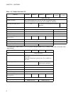
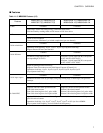
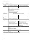
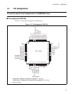
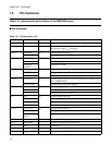
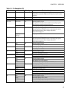
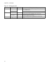
1.5 Pin Functions
Table 1.5-1 describes the pin functions of the MB90360 series.
■ Pin Functions
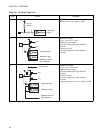
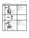
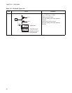
Table 1.5-1 Pin Description (1/3)
Pin number Pin name Circuit type Functional description
1AV
CC
IV
CC
power input pin for analog circuit
2 AVR - Power (Vref+) input pin for A/D converter. The power supply
should not be input V
CC
exceeding.
3 to 8 P60 to P65 H General-purpose I/O port
AN0 to AN5 Analog input pin for A/D converter.
9 to 10 P66, P67 H General-purpose I/O port
AN6, AN7 Analog input pin for A/D converter
PPGC(D),
PPGE(F)
Output pin for PPG
11 P80 F General-purpose I/O port
ADTG Trigger input pin for A/D converter
INT12R External interrupt request input pin for INT12R.
12 to 14 P50 to P52 H General-purpose I/O port (I/O circuit type of P50 is different from
that of MB90V340A)
AN8 to AN10 Analog input pin for A/D converter
15 P53 H General-purpose I/O port
AN11 Analog input pin for A/D converter
TIN3 Event input pin for reload timer 3
16 P54 H General-purpose I/O port
AN12 Analog input pin for A/D converter
TOT3 Output pin for reload timer 3
INT8 External interrupt request input pin for INT8
17 to 19 P55 to P57 H General-purpose I/O port
AN13 to AN15 Analog input pin for A/D converter
INT10, INT11,
INT13
External interrupt request input pin for INT10, INT11 and INT13
20 MD2 D Input pin for selecting operation mode
21, 22 MD1,MD0 C Input pin for selecting operation mode
23 RST E Reset input
24 V
CC
- Power input pin (3.5 V to 5.5 V)
25 V
SS
- Power input pin (0 V)