343
CHAPTER 18 8-/10-BIT A/D CONVERTER
●
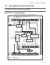
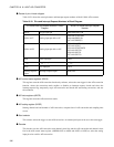
Analog channel selector
This selector selects the pin to be used for A/D conversion from the 16-channel analog input pins by
receiving a signal from the decoder.
●
Sample & hold circuit
This circuit holds the input voltage selected by the analog channel selector. By holding the input voltage
immediately after A/D conversion is started, A/D conversion is performed without being affected by the
fluctuation of the input voltage during A/D conversion.
●
D/A converter
This converter generates the reference voltage which is compared with the input voltage held in the sample
& hold circuit.
●
Comparator
This comparator compares the D/A converter output voltage with input voltage held in the sample & hold
circuit to determine the amount of voltage.
●
Controller
This circuit determines the A/D conversion value by receiving the signal indicating the amount of voltage
determined by the comparator. When the A/D conversion results are determined, the result data is stored in
the A/D data register. If an interrupt request is enabled, an interrupt is generated.


