


355
CHAPTER 18 8-/10-BIT A/D CONVERTER
The sampling time must be set according to drive impedance R
ext
connected to analog input. If the
following condition is not met, the conversion accuracy will not be guaranteed.
•R
ext
≤ 1.5kΩ :
•- 4.5 V ≤ AV
CC
< 5.5 V: The sampling time must be set greater than 0.5 µs.
• 4.0 V ≤ AV
CC
< 4.5 V: The sampling time must be set greater than 1.2 µs.
•R
ext
>
1.5kΩ : The sampling time must be set greater than T
samp
given by the following formula.
• 4.5 V ≤ AV
CC
< 5.5 V: T
samp
= (2.52 kΩ+R
ext
) × 10.7 pF × 7
• 4.0 V ≤ AV
CC
< 4.5 V: T
samp
= (13.6 kΩ+R
ext
) × 10.7 pF × 7
■ Setting of Comparing Time (CT2 to CT0 bits)
The comparing time must be set according to the analog power supply voltage AV
CC
. If the following
condition is not met, the conversion accuracy will not be guaranteed.
• 4.5 V ≤ AV
CC
< 5.5 V: The comparing time must be set greater than 1.00 µs.
• 4.0 V ≤ AV
CC
< 4.5 V: The comparing time must be set greater than 2.00 µs.
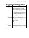
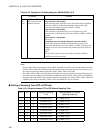
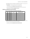
Table 18.3-7 Relation between CT2 to CT0 Bits and Comparing Time
CT2 CT1 CT0 Setting of comparing
time
Setting example (φ: Internal
operating frequency)
0 0 0 22 machine cycles φ= 20 MHz: 1.1 µs
0 0 1 33 machine cycles φ= 24 MHz: 1.4 µs
0 1 0 44 machine cycles φ= 24 MHz: 1.8 µs
0 1 1 66 machine cycles φ= 24 MHz: 2.75 µs
1 0 0 88 machine cycles φ= 8 MHz: 11.0 µs
1 0 1 132 machine cycles φ= 16 MHz: 8.25 µs
1 1 0 176 machine cycles φ= 20 MHz: 8.8 µs
1 1 1 264 machine cycles φ= 24 MHz: 11.0 µs