


210
CHAPTER 13 16-Bit I/O TIMER
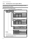
13.1 Overview of 16-bit I/O Timer
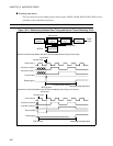
The 16-bit I/O timer consists of one 16-bit free-run timer and 4 input capture. The timer
can be performed the measurement of input pulse and external clock cycle based on the
16-bit free-run timer.
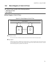
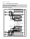
■ Module Configuration of 16-bit I/O Timer
The 16-bit I/O timer consists of the following modules:
• 16-bit free-run timer × 1 unit
16-bit free-run timer 0 (channel 0)
• Input capture × 4 units
Input capture unit 0: capture 16-bit free-run timer 0
- Input capture 0 (channel 0)
- Input capture 1 (channel 1)
- Input capture 2 (channel 2)
- Input capture 3 (channel 3)
■ Functions of 16-bit I/O Timer
●
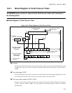
Functions of 16-bit free-run timer
The 16-bit free-run timer consists of a 16-bit up counter, a prescaler, and a control register.
The count value of the 16-bit free-run timer can be use as the base time for the input capture.
• One of eight types of the count clock cycle can be set.
• An overflow in the counter generates an interrupt request.
• The counter of the 16-bit free-run timer is cleared to "0000
H
" by reset or timer clear (TCCSL:CLR=1).
●
Functions of input capture
The input capture consists of four 16-bit capture registers and control registers corresponding to the
external input pin, and the edge detection circuit.
When the trigger edge is inputted to the external input pin, the counter value of the 16-bit free-run timer is
retained and the interrupt request is generated at the same time.
• The capture interrupt can be generated independently by each channel.
•The EI
2
OS can be started.
• Trigger edge can be selected from rising edge, falling edge, or both edges.
• Because each channel operates independently, up to 4 input measurement is performed.
• When the input signal is set to the LIN-UART, the baud rate measurement at LIN slave operation is
executed.