


340
CHAPTER 18 8-/10-BIT A/D CONVERTER
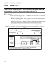
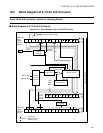
18.1 Overview of 8-/10-bit A/D Converter
The 8-/10-bit A/D converter converts the analog input voltage to a 8- or 10-bit digital
value by using the RC sequential-comparison converter system.
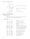
• An input signal can be selected from the input signals of the analog input pins for 16
channels.
• The start trigger can be selected from a software trigger and an external trigger.
■ Function of 8-/10-bit A/D Converter
The 8-/10-bit A/D converter converts the analog voltage (input voltage) input to the analog input pin into
an 8- or 10-bit digital value (A/D conversion).
The 8-/10-bit A/D converter has the following functions:
• A/D conversion time is a minimum of 1.9 µs
*
per channel including sampling time.
• Sampling time is a minimum of 0.5 µs
*
per channel.
• RC sequential-comparison converter system with sample & hold circuit
• Setting of 8-bit or 10-bit resolution enabled
• Analog input pin can be used up to 16 channels.
• Generates interrupt request by storing A/D conversion results in A/D data register
•Starts EI
2
OS if interrupt request generated. Use of the EI
2
OS prevents data loss even at continuous A/D
conversion.
• Selects start trigger from software trigger and external trigger (falling edge)
*: When the machine clock frequency operates at 24 MHz and AV
CC
≥ 4.5 V.
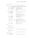
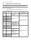
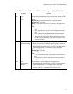
■ Conversion Modes of 8-/10-bit A/D Converter
There are 3 conversion modes of 8-/10-bit A/D converter as shown below:
Table 18.1-1 Conversion Modes of 8-/10-bit A/D Converter
Conversion
Mode
Description
Single-shot
conversion mode
A/D conversion is performed sequentially from the start channel to the end channel.
When A/D conversion for the end channel is terminated, it stops.
Continuous
conversion mode
A/D conversion is performed sequentially from the start channel to the end channel.
When A/D conversion for the end channel is terminated, it is continued after
returning to the start channel.
Pause-conversion
mode
A/D conversion is performed pausing per channel. When A/D conversion for the
end channel is terminated, A/D conversion and pause are repeated after returning to
the start channel.