


406
CHAPTER 20 LIN-UART
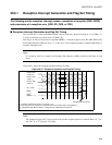
20.5 LIN-UART Interrupts
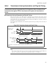
LIN-UART uses both reception and transmission interrupts. An interrupt request can be
generated for either of the following causes:
• Receive data is set in the reception data register (RDR), or a reception error occurs.
• Transmission data is transferred from the transmission data register (TDR) to the
transmission shift register and transmission is started.
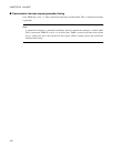
• A LIN break is detected.
The extended intelligent I/O service (EI
2
OS) is available for these interrupts.
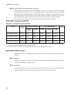
■ LIN-UART Interrupts
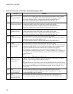
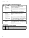
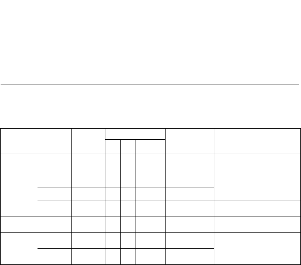
Table 20.5-1 shows the interrupt control bits and interrupt cause of the LIN-UART.
Table 20.5-1 Interrupt Control Bits and Interrupt Cause of LIN-UART
Reception/
transmission
/ICU
Interrupt
request
flag bit
Flag
register
Operation mode Interrupt cause Interrupt
cause enable
bit
How to clear the
interrupt request
0123
Reception RDRF SSR ❍❍❍❍Receive data is
written to RDR.
SSR:RIE Receive data is
read.
ORE SSR ❍❍❍❍Overrun error "1" is written to
clear reception
error flag bit
(SCR: CRE).
FRE SSR ❍❍∆ ❍ Framing error
PE SSR ❍ ×∆×Parity error
LBD ESCR ×××❍ LIN Synch break
detected
ESCR:LBIE "0" is written to
ESCR: LBD.
Transmission TDRE SSR ❍❍❍❍TDR empty SSR:TIE Write data to
TDR
Input Capture ICP0/ICP1 ICS01 ×××❍ 1st falling edge of
LIN synch field
ICS01:
ICE0/ICE1
Disable ICP0/
ICP1 temporary
ICP0/ICP1 ICS01 ×××❍ 5th falling edge of
LIN synch field
❍: Used bit
×: Unused bit
∆: Only available if ECCR/SSM = 1