


555
CHAPTER 25 EXAMPLES OF MB90F362/T(S), MB90F367/T(S) SERIAL PROGRAMMING CONNECTION
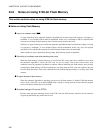
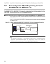
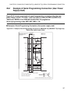
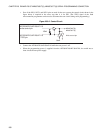
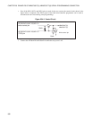
Even if the P83, P84, SIN1, SOT1, and SCK1 pins are used for the user system, the control circuit shown in
Figure 25.1-2 is required. (The /TICS signal of the flash microcontroller programmer can be used to
disconnect the user circuit during serial programming.)
Figure 25.1-2 Control Circuit
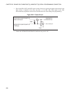
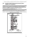
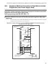
"25.2 Example of Serial Programming Connection (User Power Supply Used)" to "25.5 Example of
Minimum Connection to Flash Microcontroller Programmer (Power Supplied from Programmer)" present
examples the following 4 types of serial programming connection. See each Section as required.
• Example of serial programming connection (user power supply used)
• Example of serial programming connection (power supplied from the programmer)
• Example of minimum connection to the flash microcontroller programmer (user power supply used)
• Example of minimum connection to the flash microcontroller programmer (power supplied from the
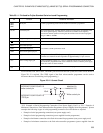
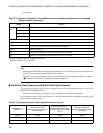
Table 25.1-1 Pin Used for Fujitsu Standard Serial on-board Programming
Pin Function Additional information
MD2,
MD1,
MD0
Mode pins Controls programming mode from the flash microcontroller programmer.
X0, X1 Oscillation pins In programming mode, the CPU internal operation clock signal is one multiple of the
PLL clock signal frequency. Therefore, because the oscillation clock frequency
becomes the internal operation clock signal, the oscillator used for serial reprogram-
ming is 4 MHz to 16 MHz.
P83, P84 Programming activation pins Input "L" level to P83 and "H" level to P84.
RST
Reset pin -
SIN1 Serial data input pin
Use UART1 as CLK synchronous mode.SOT1 Serial data output pin
SCK1 Serial clock signal input pin
C C pin
This pin is used to stabilize the power supply.
Connect to a external ceramic capacitor of approximately 0.1 µF or more.
V
CC
Power voltage supply pin If the programming voltage (5 V ± 10%) is supplied from the user system, the flash
microcontroller programmer need not be connected. Connect so that the power supply
of the user side is not short-circuited.
V
SS
GND pin Common to the ground of the flash microcontroller programmer.
User
10kΩ
Write control pin
AF220/AF210/AF120/AF110
write control pin
AF220/AF210/AF120/AF110
/TICS pin
MB90F362/T(S),
MB90F367/T(S)