562
CHAPTER 25 EXAMPLES OF MB90F362/T(S), MB90F367/T(S) SERIAL PROGRAMMING CONNECTION
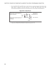
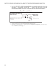
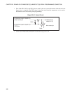
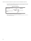
• Even if the SIN1, SOT1, and SCK1 pins are used for the user system, the control circuit shown in the
figure below is required. (The /TICS signal of the flash microcontroller programmer can be used to
disconnect the user circuit during serial programming.)
Figure 25.4-2 Control Circuit
• Connect the AF220/AF210/AF120/AF110 while the user power is off.
User
10kΩ
Write control pin
AF220/AF210/AF120/AF110
write control pin
AF220/AF210/AF120/AF110
/TICS pin
MB90F362/T(S),
MB90F367/T(S)


