


425
CHAPTER 20 LIN-UART
●
Stop bit
1- or 2-stop bit can be selected at the transmission. When 2-stop bit is selected, both stop bits is detected at
the reception. When first stop bit is detected, the RDRF bit of SSR is "1". Then, when the start bit is not
detected, the RBI bit of ECCR is set to "1", indicating no reception operation.
●
Error detection
In mode 0, the parity, overrun, and framing errors can be detected.
In mode 1, the overrun and framing errors can be detected, and the parity error cannot be detected.
●
Parity
Parity can set to add (transmission) or detect (reception) the parity bit.
The parity enable bit (SCR: PEN) is used to specify whether there is parity or not, and parity selection bit
(SCR: P) is selected the even/odd parity.
In operation mode 1, the parity cannot be used.
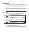
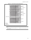
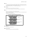
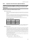
Figure 20.7-2 Transmission Data when Parity Enabled
●
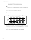
Data signal type
The data signal type is NRZ data format.
●
Data transition method
The data bit transfer method can be selected by LSB or MSB first.
SIN
1011 000
SOT
1011 001
SOT
1011 000
ST SP
ST SP
ST SP
0
0
0
0
0
0
Parity error generating
at received even parity error
(SCR:P=0)
Even parity transmitting
(SCR:P=0)
Odd parity transmitting
(SCR:P=1)
ST: Start bit, SP: Stop bit at parity ON (PEN=1)
Note: Parity can not be used at operation mode 1.