


234
CHAPTER 13 16-Bit I/O TIMER
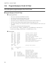
13.8 Program Example of 16-bit I/O Timer
This section gives a program example of the 16-bit I/O timer.
■ Program Example of 16-bit I/O Timer
●
Processing specification
• The cycle of a signal input to the IN0 pin is measured.
• The 16-bit free-run timer 0 and input capture 0 are used.
• The rising edge is selected as the trigger to be detected.
• The machine clock (
φ
) is 24 MHz and the count clock of the free-run timer is 4/
φ
(0.17 µs).
• The timer overflow interrupt and input capture interrupt of input capture 0 are used.
• The overflow interrupt of the 16-bit free-run timer is counted beforehand and used for the cycle
calculation.
• The cycle can be determined from the following equation:
Cycle = (overflow count × "10000
H
" + nth IPCP0 value - (n-1)th IPCP0 value) × count clock cycle
= (overflow count × 10000
H
+ nth IPCP0 value - (n-1)th IPCP0 value) × 0.17 µs
●
Coding example
ICR09 EQU 0000B9H ;Interrupt control register
ICR11 EQU 0000BBH ;Interrupt control register
DDR2 EQU 000012H ;Port 2 direction register
TCCSL EQU 007942H ;Timer control status register
TCDT EQU 007940H ;Timer data register
ICS01 EQU 000050H ;Input capture control status register
IPCP0 EQU 007920H ;Input capture register 0
IVF0 EQU TCCSL:7 ;Timer overflow generation flag bit
ICP0 EQU ICS01:6 ;Valid edge detection flag bit
DATA DSEG ABS=00H
ORG 0100H
OV_CNT RW 1H
DATA ENDS ;Overflow count counter
;
;---------Main program-------------------------------------------
CODE CSEG
START:
; ;Stack pointer (SP),
;already initialized
AND CCR,#0BFH ;Interrupt disable
MOV I:ICR09,#00H ;Interrupt level 0(strongest)
MOV I:ICR11,#00H ;Interrupt level 0(strongest)
MOV I:DDR2,#00000000B ;Port 2 direction setting
MOV I:TCCSL,#01001010B ;Count enable, Counter clear,
;Overflow, Interrupt enable,
;Count clock selection, Counter clear