163
CHAPTER 9 MEMORY ACCESS MODES
9.1.1 Mode Pins
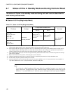
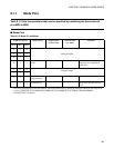
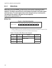
Table 9.1-2 lists the operations that can be specified by combining the three external
pins MD2 to MD0.
■ Mode Pins
Table 9.1-2 Mode Pin and Mode
Mode pin setting Mode name Reset vector
access area
External data
bus width
Remarks
MD2 MD1 MD0
0 0 0
Setting disabled0 0 1
0 1 0
0 1 1
Internal vector
mode
Internal (Mode data) Reset sequence and subsequent
sequences are controlled by
mode data.
1 0 0
Setting disabled
1 0 1
1 1 0
Flash serial
programming*
− − −
1 1 1
Flash memory
− −
Mode when parallel writer is
used
*: The serial programming of the flash memory cannot be written only by setting the mode pin. Other pin also need to be
set. See "CHAPTER 25 EXAMPLES OF MB90F362/T(S), MB90F367/T(S) SERIAL PROGRAMMING
CONNECTION" for details.


