


215
CHAPTER 13 16-Bit I/O TIMER
●
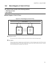
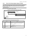
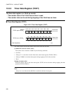
Input capture data registers 0 to 3 (IPCP0 to IPCP3)
• Input capture data register retains the counter value of the 16-bit free-run timer fetched by the capture
operation.
• Input capture data register 0 to 3 keep the counter value of the 16-bit free-run timer 0
●
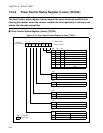
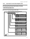
Input capture control status registers 01 to 23 (ICS01 to ICS23)
• Input capture control status register selects the trigger edge, enables the capture operation and capture
interrupt request, and checks the valid edge detection flag for each input capture.
• Input capture control status register has 2 registers, and the input capture operation of the corresponding
channel is controlled as shown in Table 13.2-2 .
●
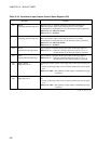
Input capture edge registers 01 to 23 (ICS01 to ICS23)
• Input capture control status register indicated the edge polarity detected by each input capture. Also, it
selects the input signal (external pin INx/LIN-UART). When input is set to the LIN-UART, the baud
rate measurement at the LIN slave operation can be performed (See "20.7.3 Operation with LIN
Function (Operation Mode 3)").
• Input capture edge register has 2 registers, and the input capture operation of the corresponding channel
is controlled as shown in Table 13.2-2 .
●
Edge detection circuit
The edge detection circuit detects the edge of the signal input to the external input pin. The detected edge
can be selected from among the rising edge, falling edge, both edges, and no detection (capture stop).
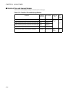
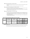
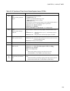
Table 13.2-2 Relationship between the Register and Pin of Input Capture
Input capture control
status register
Input capture edge
register
Input capture data
register
Input
pin
Input form
LIN-UART
Input capture
unit 0
ICS01 ICE01 IPCP0 IN0 UART0
IPCP1 IN1 UART1
ICS23 ICE23 IPCP2 IN2 -
IPCP3 IN3 -