


435
CHAPTER 20 LIN-UART
20.7.6 Master-Slave Communication Function (Multiprocessor
Mode)
LIN-UART communication with multiple CPUs connected in master-slave mode is
available for both master or slave systems in the operation mode 1.
■ Master-slave Communication Function
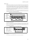
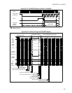
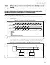
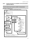
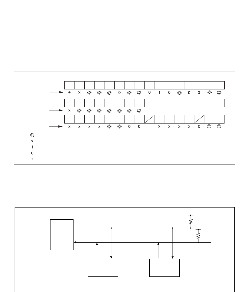
The settings shown in Figure 20.7-13 are required to operate LIN-UART in multiprocessor mode
(operation mode 1).
Figure 20.7-13 Settings for LIN-UART Operation Mode 1
●
Inter-CPU connection
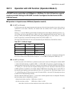
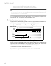
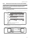
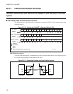
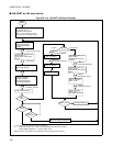
As shown in Figure 20.7-14 , a communication system consists of one master CPU and multiple slave
CPUs connected to two communication lines. LIN-UART can be used for the master or slave CPU.
Figure 20.7-14 Connection Example of LIN-UART Master-slave Communication
bit 15 bit 14 bit 13bit 12 bit 11 bit 10 bit 9 bit 8 bit 7 bit 6 bit 5 bit 4 bit 3 bit 2 bit 1 bit 0
PEN P SBL CL AD CRE RXE TXE MD1 MD0 OTO EXT
REST UPCL SCKE
SOE
PE ORE FRE
RDRF TDRE
BDS RIE TIE
LBIE LBD LBL1
SOPE
SIOP CCO
SCES
LBR MS
SCDE
SSM RBI TBILBL0
Set conversion data (during writing)
Retain reception data (during reading)
SCRn, SMRn
SSRn, TDRn/RDRn
ESCRn, ECCRn
: Used bit
: Unused bit
: Set 1
: Set 0
: Bit automatically set to correct value
n = 0, 1
Mode 1
Mode 1
Mode 1
SOT
SIN
SOT SIN
SOT SIN
Master CPU
Slave CPU#0
Slave CPU#1