


156
CHAPTER 8 LOW-POWER CONSUMPTION MODE
8.7 Status of Pins in Standby Mode and during Hold and Reset
The status of I/O pins in the standby mode and during hold and reset are described for
each memory access mode.
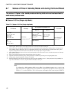
■ Status of I/O Pins (Single-chip Mode)
Note:
To set that pin to high impedance which serves either for a peripheral resource or as a port in stop
mode, watch mode, or timebase timer mode, disable the output of the peripheral resource, then set the
STP bit to "1" or set the TMD bit to "0" in the low-power consumption mode control register (LPMCR).
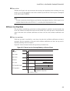
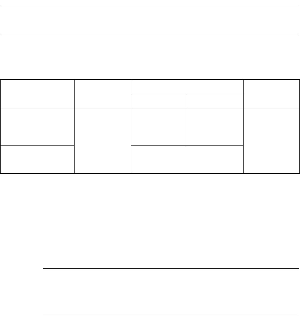
Table 8.7-1 Status of I/O Pins (Single-chip Mode)
Pin Name At sleep
At stop/watch/timebase timer
At a reset
SPL=0 SPL=1
P27 to P20
P44, P43, P41, P40
P53 to P50
P67 to P60
P87 to P85, P83
Immediately
preceding state held
*2
Input cut off
*4
/
immediately preceding
state held
*2
Input cut off
*4
/
output Hi-Z
*5
Input disabled
*3
/
output Hi-Z
*5
P42
*7
P54 to P57
P80, P82, P84
*7
Input enabled
*1
*1: Input enabled means that input function can be used. When the pin is set as input port, handle the pull-up/pull-down or input the
external signal. When the pin is set as output port, the pin is set to the same state as other pins.
*2: Indicates that either the output pins output their state as it is immediately before entering each standby mode or the input pins are
input-disabled. Output of the output state as it is means that when the resource with an output is in operation, the state of pins is
output according to the state of the resource and, when the state of output pins is output, it is held.
*3: Input disabled means that no pin value can be accepted internally because the internal circuit is off while the operation of the input
gates of pins is enabled.
*4: Input cut off means that the operation of the input gates of pins is disabled.
*5: Output Hi-Z means that the driving of pin driving transistors is disabled to place the pins in a high impedance state.
*6: In these modes, the pull-up function of the port 2 is invalid.
*7: When the INTxR bit of the external interrupt cause selection register (EISSR) is set to "1", these pins become "input enabled" in
stop mode. When the bit is set to "0", they become the same state as other pins.