389
CHAPTER 20 LIN-UART
●
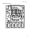
Oversampling Circuit
The oversampling circuit oversamples the incoming data at the SINn pin for five times in the asynchronous
mode. The received value is determined by majority decision of sampling time. It is switched off in
synchronous operation mode.
●
Interrupt Generation Circuit
The interrupt generation circuit administers all cases of generating a reception or transmission interrupt. If a
corresponding interrupt enable bit is set, the interrupt will be generated immediately.
●
LIN synch Break and Synchronization Field Detection Circuit
The LIN break and LIN synchronization field detection circuit detects a LIN synch break if a LIN master
node is sending a message header. If a LIN synch break is detected LBD flag bit is generated. The first and
the fifth falling edge of the LIN synchronization field is recognized by this circuit by generating an internal
signal for the Input Capture Unit to measure the actual serial clock synchronization of the transmitting
master node.
●
LIN Synch Break Generation Circuit
The LIN break generation circuit generates a LIN synch break of a determined length.
●
Bus Idle Detection circuit
The bus idle detection circuit recognizes if neither reception nor transmission is going on. In this case, the
circuit generates the special flag bits TBI and RBI.
●
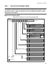
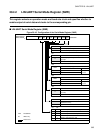
LIN-UART Serial Mode Register (SMR)
This register performs the following operations:
• Selecting the LIN-UART operation mode
• Selecting a clock input source
• Selecting if an external clock is connected "one-to-one" or connected to the reload counter
• Resetting dedicated reload timer
• Resetting the LIN-UART software (preserving the settings of the registers)
• Specifying whether to enable serial data output to the corresponding pin
• Specifying whether to enable clock output to the corresponding pin


