


158
CHAPTER 8 LOW-POWER CONSUMPTION MODE
●
PLL clock oscillation stabilization wait time
In main clock mode, the PLL multiplication circuit stops. When changing to PLL clock mode, it is
necessary to reserve the PLL clock oscillation stabilization wait time. The CPU runs in main clock mode
till the PLL clock oscillation stabilization wait time has elapsed. When the main clock mode is switched to
PLL clock mode, the PLL clock oscillation stabilization wait time is fixed at 2
14
/HCLK (HCLK: oscillation
clock).
In sub-clock mode, the main clock and PLL multiplication circuit stop. When changing to PLL clock mode,
it is necessary to reserve the main clock oscillation stabilization wait time and PLL clock oscillation
stabilization wait time. The oscillation stabilization wait time for main clock and PLL clock are counted
simultaneously according to the value specified in the oscillation stabilization wait time selection bits in the
clock selection register (CKSCR: WS1, WS0). The oscillation stabilization wait time selection bits in the
clock selection register (CKSCR: WS1, WS0) must be selected accordingly to account for the longer of the
main clock and PLL clock oscillation stabilization wait time. The PLL clock oscillation stabilization wait
time, however, requires 2
14
/HCLK or more. Set the oscillation stabilization wait time selection bits in the
clock selection register (CKSCR: WS1, WS0) to "10
B
" or "11
B
".
In PLL stop mode, the main clock and PLL multiplication circuit stop. During recovery from PLL stop
mode, it is necessary to allot the main clock oscillation stabilization wait time and PLL clock oscillation
stabilization wait time. The oscillation stabilization wait time for the main clock and PLL clock are counted
simultaneously according to the value specified in the oscillation stabilization wait time selection bits in the
clock selection register (CKSCR: WS1, WS0). The oscillation stabilization wait time selection bits in the
clock selection register (CKSCR: WS1, WS0) must be selected accordingly to account for the longer of
main clock and PLL clock oscillation stabilization wait time. The PLL clock oscillation stabilization wait
time, however, requires 2
14
/HCLK or more. Set the oscillation stabilization wait time selection bits in the
clock selection register (CKSCR: WS1, WS0) to "10
B
" or "11
B
".
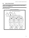
■ Clock Mode Switching
When the clock mode is switched, do not switch to other clock mode and low-power consumption mode
before this switching is completed. Confirm the completion of clock mode switching by referring to the
MCM and SCM bits of the clock selection register (CKSCR).
If the mode is switched to other clock mode or low-power consumption mode before completion of
switching, the mode may not be switched.
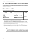
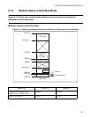
■ Notes on Accessing the Low-Power Consumption Mode Control Register (LPMCR) to
Enter the Standby Mode
●
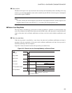
To access the low-power consumption mode control register (LPMCR) with assembler language
To set the low-power consumption mode control register (LPMCR) to enter the standby mode, use the
instruction listed in Table 8.3-2 .
The standby mode transition instruction in Table 8.3-2 must always be followed by an array of
instructions highlighted by a line below.
MOV LPMCR, #H’ xx; The low-power consumption mode transition instruction in Table 8.3-2
NOP
NOP
JMP $+3 ; Jump to the next instruction
MOV A, #H’ 10 ; Arbitrary instruction