


439
CHAPTER 20 LIN-UART
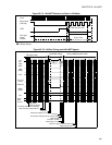
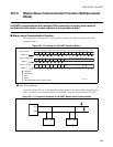
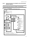
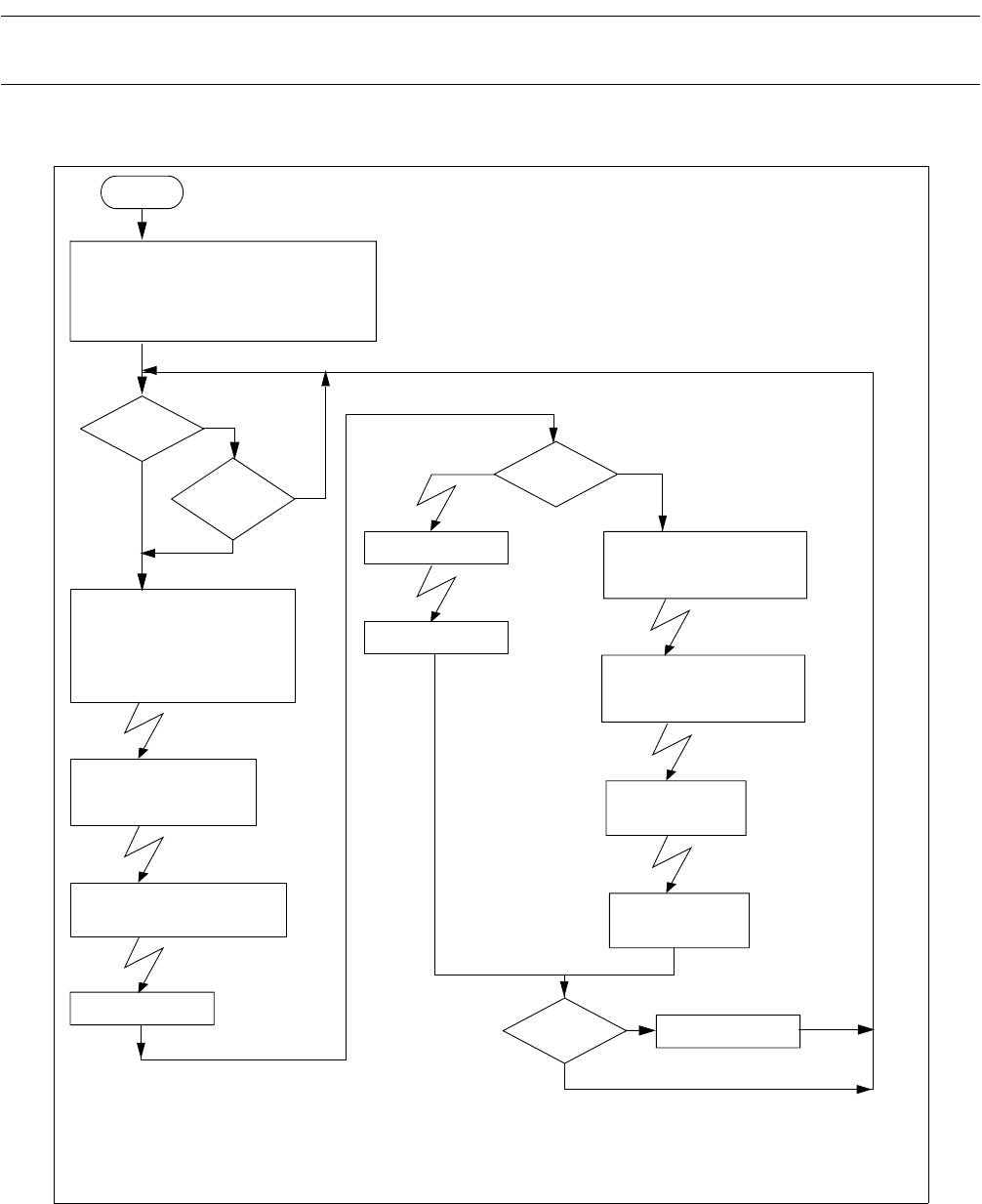
20.7.8 Sample Flowcharts for LIN-UART in LIN communication
(Operation Mode 3)
This section contains sample flowcharts for LIN-UART in LIN communication.
■ LIN-UART as LIN Master Device
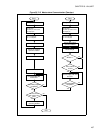
Figure 20.7-18 LIN-UART LIN Master Flowchart
Y
N
N
Y
Y
N
YN
Start
Initial setting :
Set operation mode 3
Serial data output enabled, Baud rate setting,
Synch break length setting
TXE = 1, TIE = 0, RXE = 1, RIE = 1
Send
Message?
RXE = 0
Synch break interrupt enabled
Sync Break transmission:
ECCR: LBR = 1
Synch Field transmission:
TDR = 0x55
LBD = 1
Synch Break interrupt
ID field reception*
1
Reception enabled
LBD = 0
Synch break interrupt dis-
abled
Without
error?
Error processing*
2
Data Field
reception ?
Transmission data 1 set :
TDR = Data 1
Transmission interrupt
enabled
Wake up ?
(0x80
reception)
Synch field reception
*1
Identify field set : TDR = lD
RDRF = 1
Reception interrupt
RDRF = 1
Reception interrupt
(Reception)
(Transmission)
RDRF = 1
Reception interrupt
Data 1 reception
*1
Data N reception*
1
RDRF = 1
Reception interrupt
Transmission data N set:
TDR = Data N
Transmission interrupt dis-
abled
Data 1 reception*
1
Data 1 reading
Data N reception*
1
Data N reading
TDRE = 1
Transmission interrupt
RDRF = 1
Reception interrupt
RDRF = 1
Reception interrupt
*1: If an error occurs, perform the error processing
*2: • When fre and ore is "1", write 1 to SCR: CRE bit and clear the error flag.
• When ESCR: LBD bit is "1", execute UART reset.
Note: The error is detected in each processing and take appropriate measure.