


429
CHAPTER 20 LIN-UART
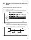
20.7.3 Operation with LIN Function (Operation Mode 3)
LIN-UART can be used either as LIN-Master or LIN-Slave. For this LIN function a special
mode is provided. Setting the LIN-UART to mode 3 configures the data format to 8N1-
LSB-first format.
■ Operation in Asynchronous LIN Mode (Operation mode 3)
●
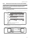
LIN-UART as LIN master
In LIN master mode, the master determines the baud rate of the whole bus, therefore slaves devices have to
synchronize to the master. Therefore, the desired baud rate remains fixed in master operation after
initialization.
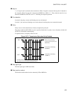
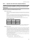
Writing a "1" into the LBR bit of the Extended Communication Control Register (ECCR) generates a 13 -
16 bit time low-level on the SOTn pin, which is the LIN synchronization break and the start of a LIN
message. Thereby the TDRE flag of the Serial Status Register (SSR) goes "0" and is reset to "1" after the
break, and generates a transmission interrupt for the CPU (if TIE of SSR is "1").
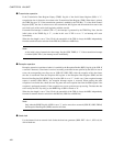
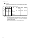
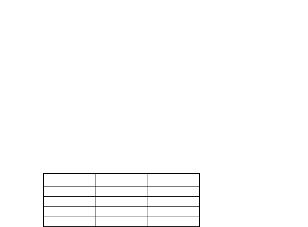
The length of the LIN break to be sent can be determined by the LBL1/0 bits of the ESCR as follows:
The Synch Field is sent as byte data of 0x55 after the LIN break. To prevent a transmission interrupt, the
0x55 can be written to the TDR just after writing the "1" to the LBR bit, although the TDRE flag is "0".
●
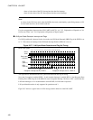
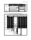
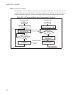
LIN-UART as LIN slave
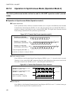
In LIN slave mode, LIN-UART has to synchronize to the master’s baud rate. If Reception is disabled (RXE
= 0) but LIN break interrupt is enabled (LBIE = 1) LIN-UART will generate a reception interrupt, if a
synchronization break from the LIN master is detected, and indicates it with the LBD flag of the ESCR to
"1". Writing "0" to this bit clears the reception interrupt request. For the calculation of the baud rate, the
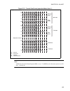
UART0 operation is explained as an example. When UART0 detects first falling edge of synch field, set
the internal signal inputted to the input capture (ICU0) to "H" and start ICU0. This internal signal is set to
"L" at fifth falling edge, ICU0 must be set to the LIN mode (ICE01). Also, the ICUO interrupt must be set
to enable and to detect both edges (ICS01).
The time when the ICU0 input signal is "1" is the value in which eight baud rates are multiplied. Therefore,
baud rate setting value is summarized as follows:
without free-run timer overflow : BGR value = (b-a)/8 -1
with free-run timer overflow : BGR value = (Max + b-a)/8-1
where Max is the free-run timer maximum value at the overflow occurs.
Table 20.7-2 LIN Break Length
LBL0 LBL1 Break length
0 0 13 bits
1 0 14 bits
0 1 15 bits
1 1 16 bits