11
CHAPTER 1 OVERVIEW
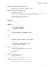
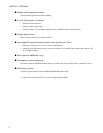
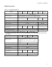
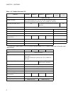
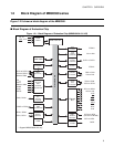
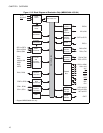
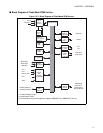
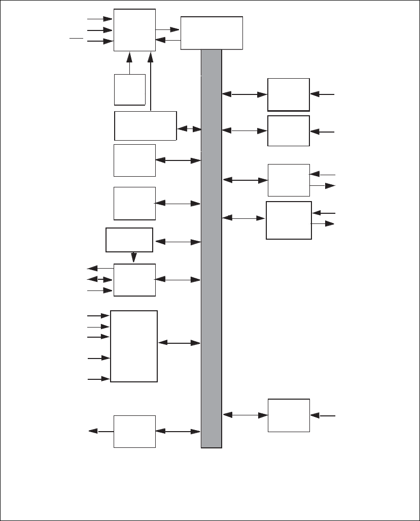
■ Block Diagram of Flash/Mask ROM Version
Figure 1.2-3 Block Diagram of Flash/Mask ROM Version
AN15 to AN0
Clock
control/
monitor *
3
RAM
3KB
ROM
64KB
UART
2 channels
8/16bit
PPG
2 channels
F
2
MC-16LX core
Input
capture
4 channels
16-bit
I/O
timer 0
CAN
controller
1 chnnal
16-bit
reload
timer
2 channels
DTP/
external
interrupt
SOT0,SOT1
SCK0,SCK1
SIN0,SIN1
PPGF(E),PPGD(C),
PPGC(D),PPGE(F)
IN0 to IN3
FRCK0
RX1
TX1
TIN2,TIN3
TOT2,TOT3
INT8,INT9R
INT10,INT11
INT12R,INT13
INT14R,INT15R
CPU operation
detection*
2
Low voltage
detection*
2
CR
oscillation
circuit
Internal data bus
AV
SS
AV
CC
Prescaler
(2 channels)
8/10-bit
A/D
converter
16 channels
X0,X1
X0A,X1A *
1
RST
AVR
ADTG
*1: Product without S-suffix
*2: Product with T-suffix
*3: CR oscillation circuit/clock supervisor supports MB90367/T(S), MB90F367/T(S) only


