


22
CHAPTER 1 OVERVIEW
●
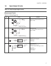
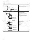
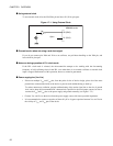
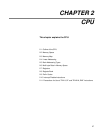
Using external clock
To use external clock, drive the X0 (X0A) pin and leave X1 (X1A) pin open.
Figure 1.7-1 Using External Clock
●
Precautions for when not using a sub clock signal
If you do not connect pins X0A and X1A to an oscillator, use pull-down handling on the X0A pin, and
leave the X1A pin open.
●
Notes on during operation of PLL clock mode
If the PLL clock mode is selected, the microcontroller attempts to be working with the free-running
frequency of self-oscillating circuit in the PLL even when there is no external oscillator or external clock
input is stopped. Performance of this operation, however, cannot be guaranteed.
●
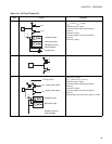
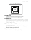
Power supply pins (V
CC
/V
SS
)
• If there are multiple V
CC
and V
SS
pins, from the point of view of device design, pins to be of the same
potential are connected the inside of the device to prevent such malfunctioning as latch up.
To reduce unnecessary radiation, prevent malfunctioning of the strobe signal due to the rise of ground
level, and to keep the recommended DC characteristics specified as the total output current, be sure to
connect the V
CC
and V
SS
pins to the power supply and ground externally (see Figure 1.7-2 ).
• Connect V
CC
and V
SS
to the device from the power supply source with lowest possible impedance.
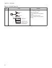
• It is recommended to connect a capacitor of about 0.1 µF as a bypass capacitor between V
CC
and V
SS
in
the vicinity of V
CC
and V
SS
pins of the device
X0 (X0A)
X1 (X1A)
MB90360 series
Open