


221
CHAPTER 13 16-Bit I/O TIMER
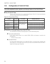
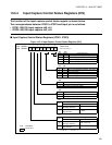
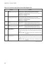
13.3.4 Input Capture Control Status Registers (ICS)
The function of the input capture control status register is shown below.
The correspondence between ICS01 to ICS23 and input pin is as follows.
• ICS01: IN0, IN1 input capture ch0, ch1
• ICS23: IN2, IN3 input capture ch2, ch3
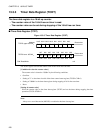
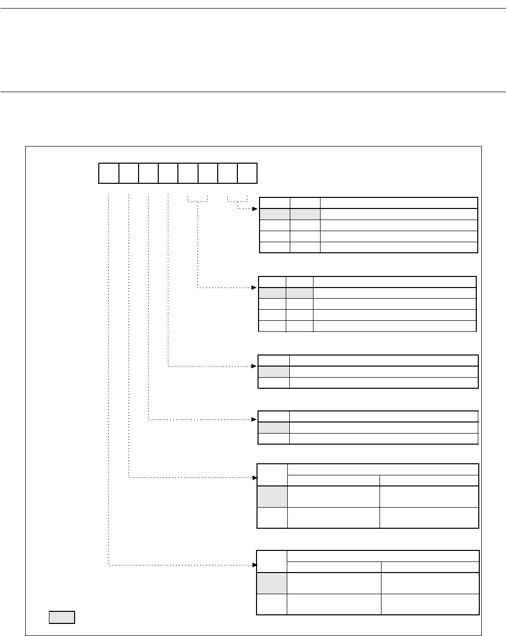
■ Input Capture Control Status Registers (ICS01, ICS23)
Figure 13.3-4 Input Capture Control Status Registers (ICS)
00000000B
453210
7
6
R/WR/WR/WR/WR/WR/W R/WR/W
ICPm ICPn ICEm ICEn EGm EGn0
1
EGm
0
EGn1
bit1 bit0
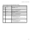
EGn1 EGn0 Edge select bit n
0 0
Without edge detection (operation stop state)
0 1 Detect rising edge
1 0 Detect falling edge
1 1 Detect both edges
bit4
ICEn Capture interrupt enable bit n
0 Input capture 0 interrupt disable
1 Input capture 0 interrupt enable
bit3 bit2
EGm1 EGm0 Edge select bit m
0 0 Without edge detection(operation stop state)
0 1 Detect rising edge
1 0 Detect falling edge
1 1 Detect both edges
bit5
ICEm Capture interrupt enable bit m
0 Input capture 1 interrupt disable
1 Input capture 1 interrupt enable
bit6
ICPn
Valid edge detection flag bit n
Read Write
0
Input capture 0 without
valid edge detection
Clear of ICP0 bit
1
Input capture 0 with valid
edge detection
No effect
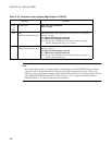
bit7
ICPm
Valid edge detection flag bit m
Read Write
0
Input capture 1 without
valid edge detection
Clear of ICP1 bit
1
Input capture 1 with valid
edge detection
No effect
Reset value
n = 0, 2 m = n + 1
Address
ICS01 : 000050
H
ICS23 : 000052
H
R/W : Read/Write
: Reset value