


350
CHAPTER 18 8-/10-BIT A/D CONVERTER
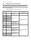
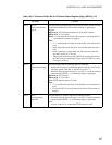
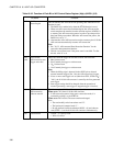
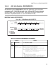
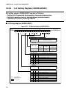
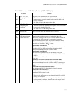
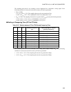
Table 18.3-3 Function of Each Bit of A/D Control Status Register (Low) (ADCS0)
Bit Name Function
bit7
bit6
MD1, MD0:
A/D conversion
mode select bits
These bits set the A/D conversion mode.
Single-shot conversion mode 1:
• The analog inputs from the start channel (ADSR0 : ANS3 to ANS0) to the end channel
(ADSR0 : ANE3 to ANE0) are A/D-converted continuously.
• The A/D conversion pauses after A/D conversion for the end channel.
• This mode can be restarted during A/D conversion.
Single-shot conversion mode 2:
• The analog inputs from the start channel (ADSR0 : ANS3 to ANS0) to the end channel
(ADSR0 : ANE3 to ANE0) are A/D-converted continuously.
• The A/D conversion pauses after A/D conversion for the end channel.
• This mode cannot be restarted during A/D conversion.
Continuous conversion mode:
• The analog inputs from the start channel (ADSR0 : ANS3 to ANS0) to the end channel
(ADSR0 : ANE3 to ANE0) are A/D-converted continuously.
• When A/D conversion for the end channel is terminated, it is continued after returning to
the analog input for the start channel.
• To terminate A/D conversion forcibly, write 0 to the A/D conversion-on flag bit in the A/D
control status register (ADCS1:BUSY).
• This mode cannot be restarted during A/D conversion.
Pause conversion mode:
• A/D conversion for the start channel (ADSR0 : ANS3 to ANS0) starts. The A/D conversion
pauses at termination of A/D conversion for a channel. When the start trigger is inputted
while A/D conversion pauses, A/D conversion for the next channel is started.
• The A/D conversion pauses at the termination of A/D conversion for the end channel.
When the start trigger is inputted while A/D conversion pauses, A/D conversion is
continued after returning to the analog input for the start channel.
• To terminate A/D conversion forcibly, write 0 to the A/D conversion-on flag bit in the A/D
control status register (ADCS1:BUSY).
• This mode cannot be restarted during A/D conversion.
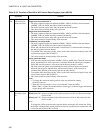
Note:
• To change the conversion mode, perform at the stop state before starting
the A/D conversion.
• When the conversion mode is set to "not restartable" (other than MD1,
MD0 ="00
B
"), it cannot be restarted with any start triggers (software trigger and external
trigger) during A/D conversion.
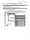
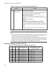
bit5 S10:
Resolution select
bit
This bit sets the resolution of the A/D conversion.
When set to "0": Set the resolution of the A/D conversion to 10-bit of A/D conversion data
bits D9 to D0.
When set to "1": Set the resolution of the A/D conversion to 8-bit of A/D conversion data
bits D7 to D0.
Note:
To change the S10 bit, perform at the stop state before starting the A/D conversion. When
the S10 bit is changed after starting A/D conversion, the converted result stored in the A/D
conversion data bit (D9 to D0) is invalid.