186
CHAPTER 11 TIMEBASE TIMER
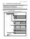
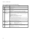
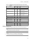
Table 11.3-1 Functions of Timebase Timer Control Register (TBTC)
Bit name Function
bit15 Reserved: reserved bit Always set this bit to "1".
bit14
bit13
Undefined bits Read: The value is undefined.
Write: No effect
bit12 TBIE:
Overflow interrupt
enable bit
This bit enables or disables an interrupt when the interval timer bit in the timebase timer
counter overflows.
When set to "0": No interrupt request is generated at an overflow (TBOF = 1).
When set to "1": An interrupt request is generated at an overflow (TBOF = 1).
bit11 TBOF:
Overflow interrupt
request flag bit
This bit indicates an overflow (carrying) in the interval timer bit in the timebase timer
counter.
When an overflow (carrying) occurs (TBOF = 1) with interrupts enabled (TBIE = 1), an
interrupt request is generated.
When set to "0": The bit is cleared.
When set to "1": Disabled. The state remains unchanged.
Read by read modify write instructions: "1" is read.
Note:
1) To clear the TBOF bit, disable interrupts (TBIE = 0) or mask interrupts using the
interrupt mask register (ILM) in the processor status.
2) The TBOF bit is cleared at a write of "0", transition to main stop mode or to PLL stop
mode, transition from subclock mode to main clock mode or to PLL clock mode,
transition from main clock mode to PLL clock mode, at a write of "0" to the timebase
timer counter clear bit (TBR), or at a reset.
bit10 TBR:
Timebase timer
counter clear bit
This bit clears all the bits in the timebase timer counter.
When set to "0" : All the bits in the timebase timer counter are cleared to "0". The
TBOF bit is also cleared.
When set to "1" : Disabled. The state remains unchanged.
Read : "1" is always read.
bit9
bit8
TBC1, TBC0:
Interval time select
bits
These bits set the cycle of the interval timer in the timebase timer counter.
• The interval time of the timebase timer is set according to the setting of the TBC1
and TBC0 bits.
• One of four time intervals can be selected.


